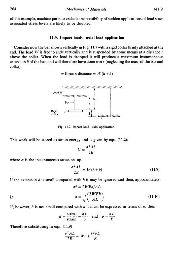
264 Mechanics of Materials s11.9 of,for example,machine parts to exclude the possibility of sudden applications of load since associated stress levels are likely to be doubled. 11.9.Impact loads-axial load application Consider now the bar shown vertically in Fig.11.7 with a rigid collar firmly attached at the end.The load W is free to slide vertically and is suspended by some means at a distance h above the collar.When the load is dropped it will produce a maximum instantaneous extension 6 of the bar,and will therefore have done work(neglecting the mass of the bar and collar) =force x distance W(h+6) Load W Rigid collar Fig.11.7.Impact load-axial application. This work will be stored as strain energy and is given by eqn.(11.2): g2AL U=2E where o is the instantaneous stress set up. o2AL =W(h+δ) 2E (11.9) If the extension 6 is small compared with h it may be ignored and then,approximately, 2 =2WEh/AL 2WEh i.e. (11.10) AL If,however,6 is not small compared with h it must be expressed in terms of o,thus stress oL E= and 6=L E Therefore substituting in eqn.(11.9) o2AL WaL 2E-Wh+E
264 Mechanics of Materials $1 1.9 of, for example, machine parts to exclude the possibility of sudden applications of load since associated stress levels are likely to be doubled. 11.9. Impact loads - axial load application Consider now the bar shown vertically in Fig. 11.7 with a rigid collar firmly attached at the end. The load W is free to slide vertically and is suspended by some means at a distance h above the collar. When the load is dropped it will produce a maximum instantaneous extension 6 of the bar, and will therefore have done work (neglecting the mass of the bar and collar) = force x distance = W (h + 6) Load W Bar-- Fig. 11.7. Impact load-axial application. This work will be stored as strain energy and is given by eqn. (1 1.2): where o is the instantaneous stress set up. (11.9) If the extension 6 is small compared with h it may be ignored and then, approximately, o2 = 2 WEhJAL i.e. u = J(F) (11.10) If, however, b is not small compared with h it must be expressed in terms of 6, thus stress OL OL E=- =- and 6 =- strain 6 E Therefore substituting in eqn. (1 1.9) O~AL WOL -- - Wh+- 2E E
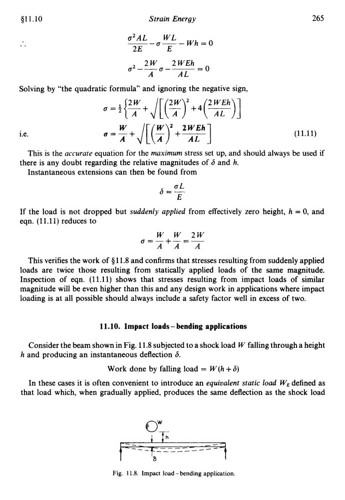
§11.10 Strain Energy 265 02AL WL 一E 2E -Wh=0 g2- 2W 2WEh A AL 0 Solving by "the quadratic formula"and ignoring the negative sign, i.e. -++2] (11.11) This is the accurate equation for the maximum stress set up,and should always be used if there is any doubt regarding the relative magnitudes of 6 and h. Instantaneous extensions can then be found from i=aL E If the load is not dropped but suddenly applied from effectively zero height,h =0,and egn.(11.11)reduces to WW 2W o-A+A=A This verifies the work of $11.8 and confirms that stresses resulting from suddenly applied loads are twice those resulting from statically applied loads of the same magnitude. Inspection of egn.(11.11)shows that stresses resulting from impact loads of similar magnitude will be even higher than this and any design work in applications where impact loading is at all possible should always include a safety factor well in excess of two. 11.10.Impact loads-bending applications Consider the beam shown in Fig.11.8 subjected to a shock load W falling through a height h and producing an instantaneous deflection 8. Work done by falling load W(h+6) In these cases it is often convenient to introduce an equivalent static load WE defined as that load which,when gradually applied,produces the same deflection as the shock load Fig.11.8.Impact load-bending application
$11.10 Strain Energy 265 U=AL WL 2E E __- a--Wh=O 2W 2WEh 02---a-- =O A AL Solving by “the quadratic formula” and ignoring the negative sign, i.e. u =E+ A J[(Z>’+T] (11.11) This is the accurate equation for the maximum stress set up, and should always be used if Instantaneous extensions can then be found from there is any doubt regarding the relative magnitudes of 6 and h. If the load is not dropped but suddenly applied from effectively zero height, h = 0, and eqn. (11.11) reduces to w w 2w a=--+-=- AA A This verifies the work of 4 11.8 and confirms that stresses resulting from suddenly applied loads are twice those resulting from statically applied loads of the same magnitude. Inspection of eqn. (11.11) shows that stresses resulting from impact loads of similar magnitude will be even higher than this and any design work in applications where impact loading is at all possible should always include a safety factor well in excess of two. 11.10. Impact loads - bending applications Consider the beam shown in Fig. 11.8 subjected to a shock load W falling through a height h and producing an instantaneous deflection 6. Work done by falling load = W(h + 6) In these cases it is often convenient to introduce an equivalent static load WE defined as that load which, when gradually applied, produces the same deflection as the shock load h -- - / _-___ ---_ ______--- H Fig. 11.8. Impact load - bending application
266 Mechanics of Materials §11.11 which it replaces,then work done by equivalent static load =WEo W(h+)=土WEδ (11.12) Thus if 6 is obtained in terms of We using the standard deflection equations of Chapter 5 for the support conditions in question,the above equation becomes a quadratic equation in one unknown WE.Hence WE can be determined and the required stresses or deflections can be found on the equivalent beam system using the usual methods for static loading,i.e.the dynamic load case has been reduced to the equivalent static load condition. Alternatively,if W produces a deflection 8,when applied statically then,by proportion, WE W 6 6=6 Or WE-5. W Substituting in egn.(11.12) wh+)=含w×司xd 82-26i-2δ,h=0 δ=δ,±√/(6,+2δh) =±(+发] (11.13) The instantaneous deflection of any shock-loaded system is thus obtained from a knowledge of the static deflection produced by an equal load.Stresses are then calculated as before. 11.11.Castigliano's first theorem for deflection Castigliano's first theorem states that: If the total strain energy of a body or framework is expressed in terms of the external loads and is partially differentiated with respect to one of the loads the result is the deflection of the point of application of that load and in the direction of that load, i.e.if U is the total strain energy,the deflection in the direction of load w=ou/ow. In order to prove the theorem,consider the beam or structure shown in Fig.11.9 with forces P,Pa,Pc,etc.,acting at points A,B,C,etc. If a,b,c,etc.,are the deflections in the direction of the loads then the total strain energy of the system is equal to the work done. U=Pa+iP8b+iPcc+... (11.14) N.B.Limitations of theory.The above simplified approach to impact loading suffers severe limitations.For example, the distribution of stress and strain under impact conditions will not strictly be the same as under static loading,and perfect elasticity of the bar will not be exhibited.These and other effects are discussed by Roark and Young in their advanced treatment of dynamic stresses:Formulas for Stress Strain,5th edition (McGraw Hill),Chapter 15
266 Mechanics of Materials $11.11 which it replaces, then work done by equivalent static load = 3 WE6 W(h+6) =$WE6 (11.12) Thus if 6 is obtained in terms of WE using the standard deflection equations of Chapter 5 for the support conditions in question, the above equation becomes a quadratic equation in one unknown WE. Hence WE can be determined and the required stresses or deflections can be found on the equivalent beam system using the usual methods for static loading, Le. the dynamic load case has been reduced to the equivalent static load condition. Alternatively, if W produces a deflection 6, when applied statically then, by proportion, Substituting in eqn. (11.12) 6 W(h+6) =~WX- x6 6, .. 6’ - 26,6 - 26,h = 0 .. 6 = 6, J(6, + 26,h) 6 = 6, [ 1 f (1 +$)’I (11.13) The instantaneous deflection of any shock-loaded system is thus obtained from a knowledge of the static deflection produced by an equal load. Stresses are then calculated as before. 11.11. Castigliano’s first theorem for deflection Castigliano’s first theorem states that: If the total strain energy of a body or framework is expressed in terms of the external loads and is partially dixerentiated with respect to one of the loads the result is the deflection of the point of application of that load and in the direction of that load, i.e. if U is the total strain energy, the deflection in the direction of load W = aU/a W. forces Pa, PB, Pc, etc., acting at points A, B, C, etc. the system is equal to the work done. In order to prove the theorem, consider the beam or structure shown in Fig. 11.9 with If a, b, c, etc., are the deflections in the direction of the loads then the total strain energy of u =+PAa+fPBb+$PcC+ . . . (11.14) N.B. Limitations oftheory. The above simplified approach to impact loading suffers severe limitations. For example, the distribution of stress and strain under impact conditions will not strictly be the same as under static loading, and perfect elasticity of the bar will not be exhibited. These and other effects are discussed by Roark and Young in their advanced treatment of dynamic stresses: Formulas for Stress & Strain, 5th edition (McGraw Hill), Chapter 15
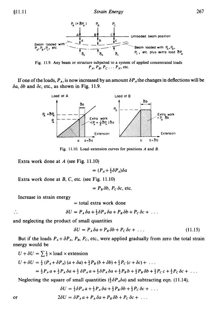
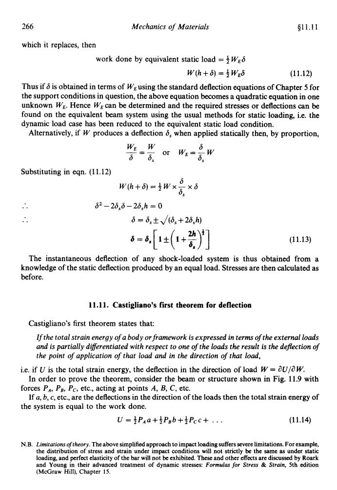
§11.11 Strain Energy 267 B(+8P) Pa A Unloaded beam position Beam loaded with Pa,etc Beam loaded with P,Pa T8. 8 Pe,etc.plus extra load 8P Fig.11.9.Any beam or structure subjected to a system of applied concentrated loads P Pg PC...PN,ctc. If one of the loads,P,is now increased by an amount &P,the changes in deflections will be δa,6bandδc,etc.,as shown in Fig.11,9. Load at A Load at B 86 8a Pa P+8R Extra work o -(8*82)8加 Extension Extension 00+8a b+8b Fig.11.10.Load-extension curves for positions A and B. Extra work done at A (see Fig.11.10) =(PA+δP)δa Extra work done at B,C,etc.(see Fig.11.10) =Paδb,Pcδc,etc. Increase in strain energy total extra work done U=PA6a+PAa+P8ob+Pcoc+... and neglecting the product of small quantities δU=P4δa+Ps6b+Pcδc+... (11.15) But if the loads P+P,Ps,Pc,etc.,were applied gradually from zero the total strain energy would be U+U=∑×load×extension U+δU=支(P4+δP)(a+δa)+Pab+δb)+Pc(c+δc)+.. =Pua+P4δa+δPua+δP4δa+Pab+Paδb+Pcc+Pcc+· Neglecting the square of small quantities (Pa)and subtracting eqn.(11.14), 6U=δP4a+2P48a+Psδb+是Pcc+. or 2δU=δPA4a+Paδa+Pgδb+Pcc+
$11.11 Strain Energy 267 *- Unlooded beam position Beam loaded with > . -__-- PA, PB,pc, e'c 1- -Beam loaded with P,,P,, Pc , etc plus extra load 8% Fig. 11.9. Any beam or structure subjected to a system of applied concentrated loads PA, P,, P, . . . P,, etc. If one of the loads, PA, is now increased by an amount SPAthe changes in deflections will be Sa, Sb and Sc, etc., as shown in Fig. 11.9. Load at A Load at B a o+80 b b+8b Fig. 11.10. Load-extension curves for positions A and E. Extra work done at A (see Fig. 11.10) = (PA+fdPA)da Extra work done at B, C, etc. (see Fig. 11.10) = PBSb, Pc6c, etc. Increase in strain energy = total extra work done .. 6u = PA6a+36PA6a+P,6b+Pc6C+ . . . and neglecting the product of small quantities 6U=PA&l+P,db+Pc6C+ . . (1 1.15) But if the loads PA+ 6PA, PB, Pc, etc., were applied gradually from zero the total strain U + SU = 14 x load x extension energy would be u+6u =3(PA+6PA)(a+ba)+4P,(b+6b)+3Pc(C+6C)+ . . . = +PA a ++PA 6a ++ 6P, a ++SPA ha +:p, b ++P,6b +4Pcc +iP,6C + . . . Neglecting the square of small quantities (f6PAGa) and subtracting eqn. (1 1.14), 6U=+6PAa+3PA6a+3P,6b+4Pc6C+ . . . or 26u = 6PAa+PA6a+Pg6b+PCbC+ . .
268 Mechanics of Materials §11.12 Subtracting eqn.(11.15), SU 5U=δPa8Pa aU or,in the limit, aPA =4 i.e.the partial differential of the strain energy U with respect to P,gives the deflection under and in the direction of P.Similarly, aU aU =b and =c,etc. OPB OPc In most beam applications the strain energy,and hence the deflection,resulting from end loads and shear forces are taken to be negligible in comparison with the strain energy resulting from bending(torsion not normally being present), M2 U= ds 2E1 OU OU OM (2M OM p=aM×aP= 2EI ds× OP i.e. 5-0UM OM ds OP-EI OP (11.16) which is the usual form of Castigliano's first theorem.The integral is evaluated as it stands to give the deflection under an existing load P,the value of the bending moment M at some general section having been determined in terms of P.If no general expression for M in terms of P can be obtained to cover the whole beam then the beam,and hence the integral limits,can be divided into any number of convenient parts and the results added.In cases where the deflection is required at a point or in a direction in which there is no load applied,an imaginary load P is introduced in the required direction,the integral obtained in terms of P and then evaluated with P equal to zero. The above procedures are illustrated in worked examples at the end of this chapter. 11.12.“Unit-load”method It has been shown in $11.11 that in applications where bending provides practically all of the total strain energy of a system 6= [M OM JEi aw ds Now W is an applied concentrated load and M will therefore include terms of the form Wx,where x is some distance from W to the point where the bending moment(B.M.)is required plus terms associated with the other loads.The latter will reduce to zero when partially differentiated with respect to W since they do not include W. 0 Now (Wx)=x=1xx
268 Mechanics of Materials $11.12 Subtracting eqn. (1 1.15), or, in the limit, i.e. the partial differential of the strain energy U with respect to PA gives the deflection under and in the direction of PA. Similarly, In most beam applications the strain energy, and hence the deflection, resulting from end loads and shear forces are taken to be negligible in comparison with the strain energy resulting from bending (torsion not normally being present), i.e. dU - dU x-=[-dsx- dM 2M dM aP dM dP 2EI ap (11.16) which is the usual form of Castigliano’s first theorem. The integral is evaluated as it stands to give the deflection under an existing load P, the value of the bending moment M at some general section having been determined in terms of P. If no general expression for M in terms of P can be obtained to cover the whole beam then the beam, and hence the integral limits, can be divided into any number of convenient parts and the results added. In cases where the deflection is required at a point or in a direction in which there is no load applied, an imaginary load P is introduced in the required direction, the integral obtained in terms of P and then evaluated with P equal to zero. The above procedures are illustrated in worked examples at the end of this chapter. 11.12. “Unit-load” method It has been shown in $1 1.11 that in applications where bending provides practically all of the total strain energy of a system M dM 6= ---& s EI aw Now W is an applied concentrated load and M will therefore include terms of the form Wx, where x is some distance from W to the point where the bending moment (B.M.) is required plus terms associated with the other loads. The latter will reduce to zero when partially differentiated with respect to W since they do not include W. Now d __ ( WX) = x = 1 xx dW