CHAPTER 13 COMPLEX STRESSES Summary The normal stress o and shear stress t on oblique planes resulting from direct loading are a=a sin20 and t=sin 20 The stresses on oblique planes owing to a complex stress system are: normal stress =(ox+)+(ax-)cos 20+txy sin 20 shear stress =(x-)sin 20-tx cos 20 The principal stresses (i.e.the maximum and minimum direct stresses)are then o1=(ox+0,)+√[(ax-,2+4t3] 02=(ox+oy)-√[(ox-0,)2+4t] and these occur on planes at an angle e to the plane on which ax acts,given by either tan28=,2” (ox-0) or tan0=p-0x where p=a1,or o2,the planes being termed principal planes.The principal planes are always at 90 to each other,and the planes of maximum shear are then located at 45 to them. The maximum shear stress is tmx=2√/[(ox-0y)2+4r,]=(o1-02) In problems where the principal stress in the third dimension a3 either is known or can be assumed to be zero,the true maximum shear stress is then (greatest principal stress-least principal stress) Normal stress on plane of maximum shear =(+ Shear stress on plane of maximum direct stress (principal plane)=0 Most problems can be solved graphically by Mohr's stress circle.All questions which are capable of solution by this method have been solved both analytically and graphically. 13.1.Stresses on oblique planes Consider the general case,shown in Fig.13.1,of a bar under direct load F giving rise to stress o,vertically. 326
CHAPTER 13 COMPLEX STRESSES Summary The normal stress a and shear stress z on oblique planes resulting from direct loading are a = ay sin’ 8 and z = 30, sin 28 The stresses on oblique planes owing to a complex stress system are: normal stress = +(a, + ay) ++(ax - a,) cos 28 + zXy sin 28 shear stress = +(a, - cy) sin 28 - zXy cos 28 The principal stresses (i.e. the maximum and minimum direct stresses) are then a1 = *(a, + a,,) + ,J[ (a, -ay)’ + 45py] 0’ = *(a, + (ty) - $J[ (6, - o~)’ + 4~:,] and these occur on planes at an angle 0 to the plane on which a, acts, given by either where aP = alr or a’, the planes being termed principal planes. The principal planes are always at 90” to each other, and the planes of maximum shear are then located at 45” to them. The maximum shear stress is zmax= 3JC(~x-~,)2+4~~,l = a@, -a’) In problems where the principal stress in the third dimension u3 either is known or can be assumed to be zero, the true maximum shear stress is then +(greatest principal stress - least principal stress) Normal stress on plane of maximum shear = $(a, + a,) Shear stress on plane of maximum direct stress (principal plane) = 0 Most problems can be solved graphically by Mohr’s stress circle. All questions which are capable of solution by this method have been solved both analytically and graphically. 13.1. Stresses on oblique planes Consider the general case, shown in Fig. 13.1, of a bar under direct load F giving rise to stress by vertically. 326
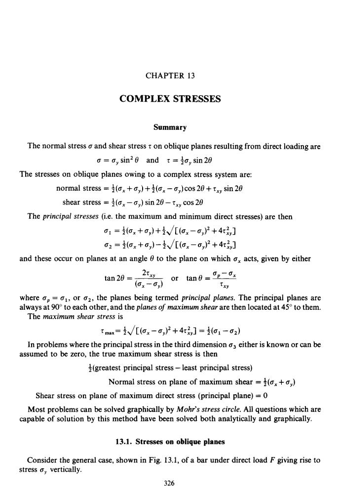
§13.2 Complex Stresses 327 -Unit depth Fig.13.1.Bar subjected to direct stress,showing stresses acting on any inclined plane. Let the block be of unit depth;then considering the equilibrium of forces on the triangular portion ABC: resolving forces perpendicular to BC, og×BC×1=g,×AB×1×sin6 But AB BC sin 0, ae=a,sin20 (13.1) Now resolving forces parallel to BC, tg×BC×1=o,×AB×1Xcos6 Again AB BC sin 0. Te =y sin 0 cos0 =t,sin 20 (13.2) The stresses on the inclined plane,therefore,are not simply the resolutions of oy perpendicular and tangential to that plane.The direct stress has a maximum value of when6=90°whilst the shear stress te has a maximum value of to,whenθ=45°, Thus any material whose yield stress in shear is less than half that in tension or compression will yield initially in shear under the action of direct tensile or compressive forces. This is evidenced by the typical"cup and cone"type failure in tension tests of ductile specimens such as low carbon steel where failure occurs initially on planes at 45 to the specimen axis.Similar effects occur in compression tests on,for example,timber where failure is again due to the development of critical shear stresses on 45 planes. 13.2.Material subjected to pure shear Consider the element shown in Fig.13.2 to which shear stresses have been applied to the sides AB and DC.Complementary shear stresses of equal value but of opposite effect are then set up on sides AD and BC in order to prevent rotation of the element.Since the applied and complementary shears are of equal value on the x and y planes,they are both given the symbol tx
$13.2 c Complex Stresses 327 t Fig. 13.1. Bar subjected to direct stress, showing stresses acting on any inclined plane. Let the block be of unit depth; then considering the equilibrium of forces on the triangular resolving forces perpendicular to BC, portion ABC: oo x BC x 1 = Q,, x AB x 1 x sin8 But AB = BC sin 8, .. bg = uy sin2 8 (13.1) Now resolving forces parallel to BC, T,x~cxi =o,,x~~xixcose Again AB = BC sin 8, .. to = sin 8 cos 8 = 30, sin 28 The stresses on the inclined plane, therefore, are not simply the resolutions of o, perpendicular and tangential to that plane. The direct stress uo has a maximum value of Q, when 8 = 90" whilst the shear stress q, has a maximum value of 30, when 8 = 45". Thus any material whose yield stress in shear is less than half that in tension or compression will yield initially in shear under the action of direct tensile or compressive forces. This is evidenced by the typical "cup and cone" type failure in tension tests of ductile specimens such as low carbon steel where failure occurs initially on planes at 45" to the specimen axis. Similar effects occur in compression tests on, for example, timber where failure is again due to the development of critical shear stresses on 45" planes. (1 3.2) 13.2. Material subjected to pure shear Consider the element shown in Fig. 13.2 to which shear stresses have been applied to the sides AB and DC. Complementary shear stresses of equal value but of opposite effect are then set up on sides AD and BC in order to prevent rotation of the element. Since the applied and complementary shears are of equal value on the x and y planes, they are both given the symbol rXy
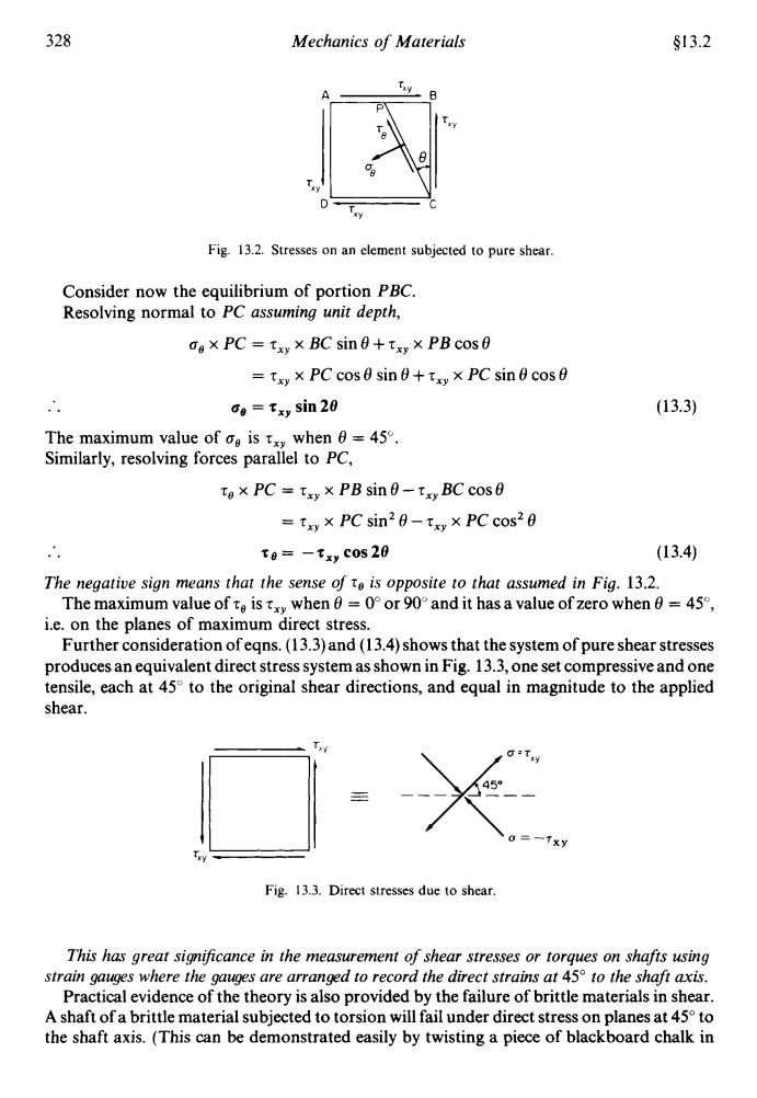
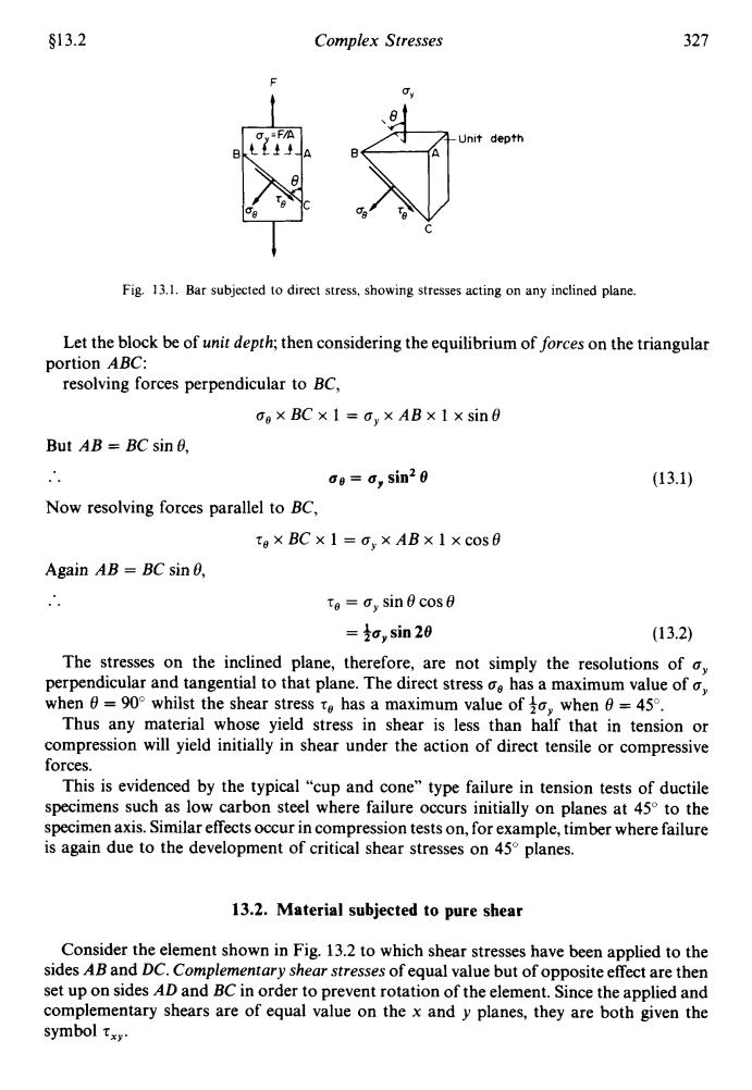
328 Mechanics of Materials S13.2 A y Fig.13.2.Stresses on an element subjected to pure shear. Consider now the equilibrium of portion PBC. Resolving normal to PC assuming unit depth, dox PC=txy×BC sin0+txy×PB cos0 =txy×PC cos sinθ+txy×PC sin0 cos0 o=txy sin 20 (13.3) The maximum value of ce is txy when 6=45. Similarly,resolving forces parallel to PC, tox PC txy x PB sin 0-txy BC cos0 =txw×PC sin20-ty×PCcos20 to=-txy Cos 20 (13.4) The negative sign means that the sense of t is opposite to that assumed in Fig.13.2. The maximum value of te is xy when=0or 90and it has a value of zero when=45, i.e.on the planes of maximum direct stress. Further consideration ofegns.(13.3)and(13.4)shows that the system of pure shear stresses produces an equivalent direct stress system as shown in Fig.13.3,one set compressive and one tensile,each at 45 to the original shear directions,and equal in magnitude to the applied shear. G-Twy 451 0=--Txy Fig.13.3.Direct stresses due to shear. This has great significance in the measurement of shear stresses or torques on shafts using strain gauges where the gauges are arranged to record the direct strains at 45 to the shaft axis. Practical evidence of the theory is also provided by the failure of brittle materials in shear. A shaft of a brittle material subjected to torsion will fail under direct stress on planes at 45to the shaft axis.(This can be demonstrated easily by twisting a piece of blackboard chalk in
328 Mechanics of Materials $13.2 Fig. 13.2. Stresses on an element subjected to pure shear. Consider now the equilibrium of portion PBC. Resolving normal to PC assuming unit depth, no x PC = zxy x BC sin8+zxy x PB cos8 (13.3) = zxy x PC cos 8 sin 8 + zxy x PC sin 8 cos 8 .. The maximum value of no is zxy when 8 = 45". Similarly, resolving forces parallel to PC, q, = zXy sin 28 z, x PC = zxy x PB sin 8 - zxy BC cos 8 = zxy x PC sin2 8 - zXy x PC cos2 e .. -zxycos28 (13.4) The negative sign means that the sense of To is opposite to that assumed in Fig. 13.2. The maximum value of 7, is zxy when 8 = 0" or 90" and it has a value of zero when 8 = 45", i.e. on the planes of maximum direct stress. Further consideration of eqns. (13.3) and (13.4) shows that the system of pure shear stresses produces an equivalent direct stress system as shown in Fig. 13.3, one set compressive and one tensile, each at 45" to the original shear directions, and equal in magnitude to the applied shear. XY Fig. 13.3. Direct stresses due to shear. This has great sign@ance in the measurement of shear stresses or torques on shafts using strain gauges where the gauges are arranged to record the direct strains at 45" to the shaft axis. Practical evidence of the theory is also provided by the failure of brittle materials in shear. A shaft of a brittle material subjected to torsion will fail under direct stress on planes at 45" to the shaft axis. (This can be demonstrated easily by twisting a piece of blackboard chalk in
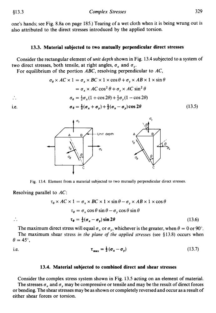
§13.3 Complex Stresses 329 one's hands;see Fig.8.8a on page 185.)Tearing of a wet cloth when it is being wrung out is also attributed to the direct stresses introduced by the applied torsion. 13.3.Material subjected to two mutually perpendicular direct stresses Consider the rectangular element of unit depth shown in Fig.13.4 subjected to a system of two direct stresses,both tensile,at right angles,ox and o,. For equilibrium of the portion ABC,resolving perpendicular to AC, og×AC×1=ox×BC×1×cos0+o,×AB×1×sin0 =ox×AC cos29+o,×AC sin20 0g=ox(1+cos20+o,(1-cos20) i.e. 00=(ax+0,)+(ox-c,)c0s20 (13.5) 6 Unit depth Fig.13.4.Element from a material subjected to two mutually perpendicular direct stresses. Resolving parallel to AC: ta×AC×1=ox×BC×1×sin8-o,×AB×1Xcos0 te=x cos sin0-ay cos 0 sin0 tg=(ox-o,)sin20 (13.6) The maximum direct stress will equal ox or whichever is the greater,when=0or 90. The maximum shear stress in the plane of the applied stresses (see $13.8)occurs when 0=45°, i.e. tmx=是(ox-0,) (13.7) 13.4.Material subjected to combined direct and shear stresses Consider the complex stress system shown in Fig.13.5 acting on an element of material. The stresses and may be compressive or tensile and may be the result of direct forces or bending.The shear stresses may be as shown or completely reversed and occur as a result of either shear forces or torsion
$13.3 Complex Stresses 329 one's hands; see Fig. 8.8a on page 185.) Tearing of a wet cloth when it is being wrung out is also attributed to the direct stresses introduced by the applied torsion. 13.3. Material subjected to two mutually perpendicular direct stresses Consider the rectangular element of unit depth shown in Fig. 13.4 subjected to a system of For equilibrium of the portion ABC, resolving perpendicular to AC, two direct stresses, both tensile, at right angles, ax and ay. box ACx 1 = a, x BC x 1 xcos8+oY x ABx 1 x sin8 = a, x AC cos' 8 +ay x AC sin'8 .. = +ox (1 + COS 28) + icy (1 - cos 28) i.e. ug = ~(ux+uy)+~(ux-ubg)c~~2e (1 3.5) t i Fig. 13.4. Element from a material subjected to two mutually perpendicular direct stresses. Resolving parallel to AC: zo x AC x 1 = a, x BC x 1 x sine-a, x AB x 1 x cos8 .. zo = a, cos 8 sin 8 - ay cos 8 sin 8 re = $(ux - uy) sin 28 (13.6) The maximum direct stress will equal a, or by, whichever is the greater, when 8 = 0 or 90". The maximum shear stress in the plane of the applied stresses (see $13.8) occurs when e = 450, i.e. rm.x = 4 (ax - by) (13.7) 13.4. Material subjected to combined direct and shear stresses Consider the complex stress system shown in Fig. 13.5 acting on an element of material. The stresses a, and ay may be compressive or tensile and may be the result of direct forces or bending. The shear stresses may be as shown or completely reversed and occur as a result of either shear forces or torsion

330 Mechanics of Materials §13.4 y Fig.13.5.Two-dimensional complex stress system. The diagram thus represents a complete stress system for any condition of applied load in two dimensions and represents an addition of the stress systems previously considered in §§13.2and13.3. The formulae obtained in these sections may therefore be combined to give o=(ax+a)+(ax-a)cos 20+ixy sin 20 (13.8) and to=(ox-a)sin 20-txy cos 20 (13.9) The maximum and minimum stresses which occur on any plane in the material can now be determined as follows: For oe to be a maximum or minimum doe=0 de Now o=(ox+)+(ax-G)cos 20+txy sin 20 do =-(-,sin 20+2tx cos20-0 do or tan 20 Lisy (13.10) (ax-0,) from Fig.13.6 sin 20 = 2txy √/[(ox-o,)2+4t,] (x-0) cos 20=- √/[ax-,)2+4t] (G,-0+4Ty 2y 28 (-cy} Fig.13.6
330 Mechanics of Materials $1 3.4 t Fig. 13.5. Two-dimensional complex stress system The diagram thus represents a complete stress system for any condition of applied load in two dimensions and represents an addition of the stress systems previously considered in Gg13.2 and 13.3. The formulae obtained in these sections may therefore be combined to give ug = +(u, + u,) ++(u, - u,) cos 28 +7,, sin 28 (1 3.8) and zg= ~(u,-u,)sin28--z,,cos28 (1 3.9) determined as follows: The maximum and minimum stresses which occur on any plane in the material can now be For ag to be a maximum or minimum Now ~ =o 40 dg = +(a, + a,) ++(a, - a,) COS 20 + T,~ sin 20 3 = - (a, - ay) sin 20 + 25,, cos 20 = o de .. or .'. from Fig. 13.6 sin20 = - JW, - + 4e,1 (1 3.10) (u,-u,) Fig. 13.6