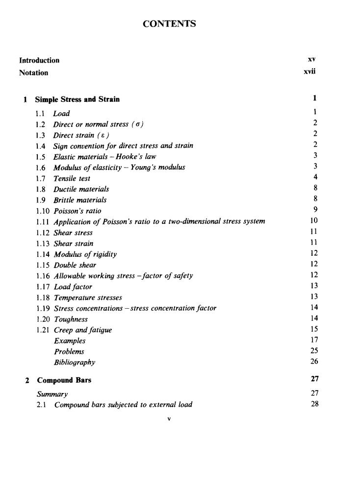
CONTENTS Introduction XV Notation 1 Simple Stress and Strain 1 1.I Load 1 1.2 Direct or normal stress (a) 2 1.3 Direct strain (8) 2 1.4 Sign convention for direct stress and strain 2 1.5 Elastic materials-Hooke's law 3 1.6 Modulus of elasticity-Young's modulus 3 1.7 Tensile test 4 1.8 Ductile materials 8 1.9 Brittle materials 8 1.10 Poisson's ratio 9 1.11 Application of Poisson's ratio to a two-dimensional stress system 10 1.12 Shear stress 11 1.13 Shear strain 11 1.14 Modulus of rigidity 12 1.15 Double shear 12 1.16 Allowable working stress -factor of safety 12 1.17 Load factor 13 1.18 Temperature stresses 13 1.19 Stress concentrations-stress concentration factor 14 1.20 Toughness 14 1.21 Creep and fatigue 15 Examples 17 Problems 25 Bibliography 26 2 Compound Bars 27 Summary 27 2.1 Compound bars subjected to external load 28
CONTENTS Introduction Notation xv XVii 1 Simple Stress and Strain 1.1 Load 1.2 Direct or normal stress (a) 1.3 Direct strain (E ) 1.4 Sign convention for direct stress and strain 1.5 Elastic materials - Hooke’s law 1.6 Modulus of elasticity - Young’s modulus 1.7 Tensile test 1.8 Ductile materials 1.9 Brittle materials 1.10 Poisson’s ratio 1.1 1 Application of Poisson’s ratio to a two-dimensional stress system 1.12 Shear stress 1.1 3 Shear strain 1.14 Modulus of rigidity 1,15 Double shear 1.16 Allowable working stress -factor of safety 1.17 Load factor 1.18 Temperature stresses 1.19 Stress concentrations -stress concentration factor 1.20 Toughness 1.21 Creep and fatigue Examples Problems Bibliography 2 Compound Bars Summary 2.1 Compound bars subjected to external load V 1 1 2 2 2 3 3 4 8 8 9 10 11 11 12 12 12 13 13 14 14 15 17 25 26 27 27 28

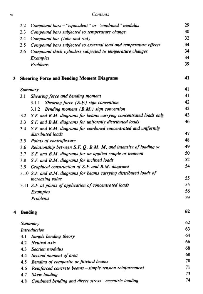
vi Contents 2.2 Compound bars-"equivalent"or "combined"modulus 29 2.3 Compound bars subjected to temperature change 30 2.4 Compound bar (tube and rod) 32 2.5 Compound bars subjected to external load and temperature effects 34 2.6 Compound thick cylinders subjected to temperature changes 34 Examples 4 Problems 3 Shearing Force and Bending Moment Diagrams 41 Summary 41 3.1 Shearing force and bending moment 41 3.1.1 Shearing force (S.F.)sign convention 42 3.1.2 Bending moment (B.M.)sign convention 42 3.2 S.F.and B.M.diagrams for beams carrying concentrated loads only 43 3.3 S.F.and B.M.diagrams for uniformly distributed loads 46 3.4 S.F.and B.M.diagrams for combined concentrated and uniformly distributed loads 47 3.5 Points of contraflexure 48 3.6 Relationship between S.F.O,B.M.M,and intensity of loading w 49 3.7 S.F.and B.M.diagrams for an applied couple or moment 50 3.8 S.F.and B.M.diagrams for inclined loads 52 3.9 Graphical construction of S.F.and B.M.diagrams 54 3.10 S.F.and B.M.diagrams for beams carrying distributed loads of increasing value 55 3.11 S.F.at points of application of concentrated loads 55 Examples 56 Problems 59 4 Bending 62 Summary 62 Introduction 63 4.1 Simple bending theory 64 4.2 Neutral axis 66 4.3 Section modulus 68 4.4 Second moment of area 68 4.5 Bending of composite or flitched beams 70 4.6 Reinforced concrete beams-simple tension reinforcement 71 4.7 Skew loading 73 4.8 Combined bending and direct stress-eccentric loading 74
vi Contents 2.2 Compound bars - ‘<equivalent ” or “combined” modulus 2.3 Compound bars subjected to temperature change 2.4 Compound bar (tube and rod) 2.5 Compound bars subjected to external load and temperature effects 2.6 Compound thick cylinders subjected to temperature changes Examples Problems 3 Shearing Force and Bending Moment Diagrams Summary 3.1 Shearing force and bending moment 3.1.1 Shearing force (S.F.) sign convention 3.1.2 Bending moment (B.M.) sign convention 3.2 S.F. and B.M. diagrams for beams carrying concentrated loads only 3.3 S.F. and B.M. diagrams for uniformly distributed loads 3.4 S.F. and B.M. diagrams for combined concentrated and uniformly distributed loads 3.5 Points of contrafexure 3.6 Relationship between S.F. Q, B.M. M, and intensity of loading w 3.1 S.F. and B.M. diagrams for an applied couple or moment 3.8 S.F. and B.M. diagrams for inclined loa& 3.9 Graphical construction of S.F. and B.M. diagrams 3.10 S.F. and B.M. diagrams for beams carrying distributed loads of increasing value 3.1 1 S.F. at points of application of concentrated loads Examples Problems 4 Bending Summary Introduction 4.1 Simple bending theory 4.2 Neutral axis 4.3 Section modulus 4.4 Second moment of area 4.5 4.6 4.1 Skew loading 4.8 Bending of composite or fitched beams Reinforced concrete beams -simple tension reinforcement Combined bending and direct stress -eccentric loading 29 30 32 34 34 34 39 41 41 41 42 42 43 46 47 48 49 50 52 54 55 55 56 59 62 62 63 64 66 68 68 70 71 73 74

Contents vii 4.9 "Middle-quarter"and "middle-third"rules 76 4.10 Shear stresses owing to bending 77 4.11 Strain energy in bending 78 4.12 Limitations of the simple bending theory 78 Examples 79 Problems 88 5 Slope and Deflection of Beams 92 Summary Introduction 9 5.1 Relationship between loading,S.F.,B.M.,slope and deflection 94 5.2 Direct integration method 97 5.3 Macaulay's method 102 5.4 Macaulay's method for u.d.I's 105 5.5 Macaulay's method for beams with u.d.1.applied over part of the beam 106 5.6 Macaulay's method for couple applied at a point 106 5.7 Mohr's "area-moment"method 108 5.8 Principle of superposition 112 5.9 Energy method 112 5.10 Maxwell's theorem of reciprocal displacements 112 5.11 Continuous beams-Clapeyron's "three-moment"equation 115 5.12 Finite difference method 118 5.13 Deflections due to temperature effects 119 Examples 123 Problems 138 6 Built-in Beams 140 Summary 140 Introduction 141 6.1 Built-in beam carrying central concentrated load 141 6.2 Built-in beam carrying uniformly distributed load across the span 142 6.3 Built-in beam carrying concentrated load offset from the centre 143 6.4 Built-in beam carrying a non-uniform distributed load 145 6.5 Advantages and disadvantages of built-in beams 146 6.6 Effect of movement of supports 146 Examples 147 Problems 152
Contents vii 4.9 4.10 Shear stresses owing to bending 4.1 1 Strain energy in bending 4.12 Limitations of the simple bending theory “Middle-quarter ” and “middle-third ” rules Examples Problems 5 Slope and Deflection of Beams Summary Introduction 5.1 5.2 Direct integration method 5.3 MacaulayS method 5.4 Macaulay’s method for u.d.ls 5.5 Macaulay’s method for beams with u.d.1. applied over part of the beam 5.6 Macaulay’s method for couple applied at a point 5.7 Mohr’s “area-moment” method 5.8 Principle of superposition 5.9 Energy method 5.10 Maxwell’s theorem of reciprocal displacements 5.1 1 Continuous beams - CIapeyron’s “three-moment ” equation 5.12 Finite difference method 5.13 Defections due to temperature effects Relationship between loading, S.F., B.M., slope and akfection Examples Problems 6 Built-in Beams Summary Introduction 6.1 Built-in beam carrying central concentrated load 6.2 Built-in beam carrying uniformly distributed load across the span 6.3 Built-in beam carrying concentrated load offset from the centre 6.4 Built-in beam carrying a non-uniform distributed load 6.5 Advantages and disadvantages of built-in beams 6.6 Effect of movement of supports Examples Problems 76 77 78 78 79 88 92 92 94 94 97 102 105 106 106 108 112 112 112 115 118 119 123 138 140 140 141 141 142 143 145 146 146 147 152

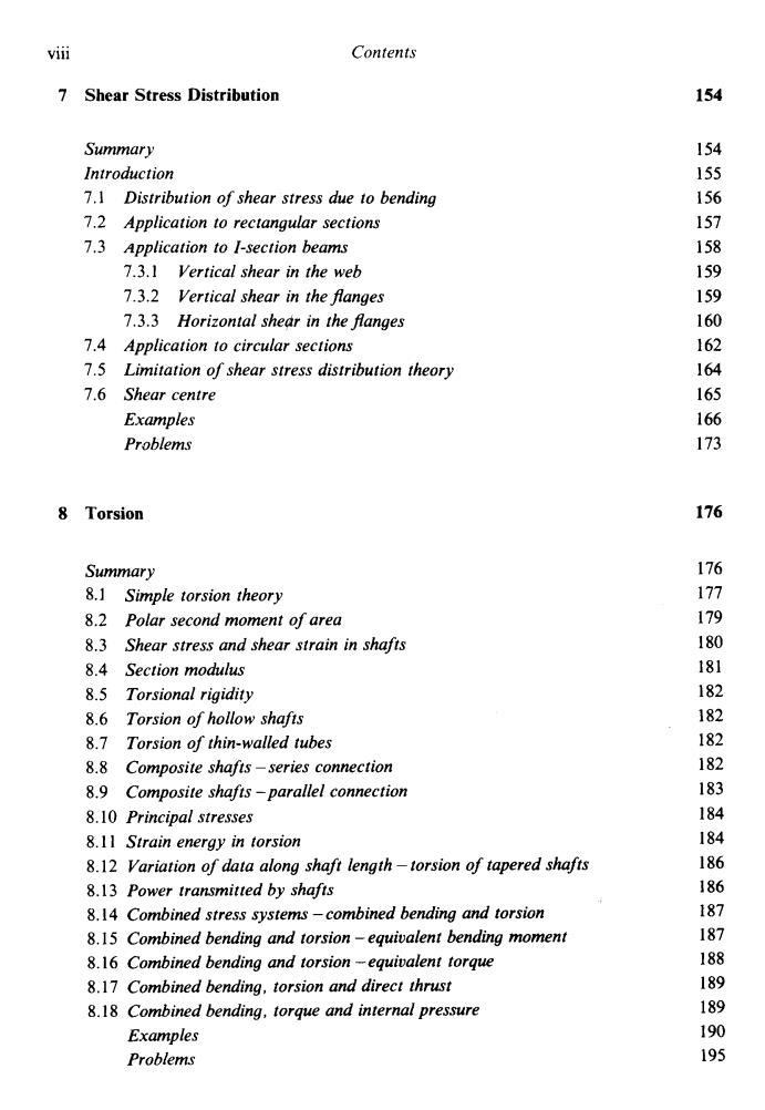
viii Contents 7 Shear Stress Distribution 154 Summary 154 Introduction 155 7.1 Distribution of shear stress due to bending 156 7.2 Application to rectangular sections 157 7.3 Application to I-section beams 158 7.3.1 Vertical shear in the web 159 7.3.2 Vertical shear in the flanges 159 7.3.3 Horizontal shear in the flanges 160 7.4 Application to circular sections 162 7.5 Limitation of shear stress distribution theory 164 7.6 Shear centre 165 Examples 166 Problems 173 8 Torsion 176 Summary 176 8.1 Simple torsion theory 177 8.2 Polar second moment of area 179 8.3 Shear stress and shear strain in shafts 180 8.4 Section modulus 181 8.5 Torsional rigidity 182 8.6 Torsion of hollow shafts 182 8.7 Torsion of thin-walled tubes 182 8.8 Composite shafts-series connection 182 8.9 Composite shafts-parallel connection 183 8.10 Principal stresses 184 8.11 Strain energy in torsion 184 8.12 Variation of data along shaft length-torsion of tapered shafts 186 8.13 Power transmitted by shafts 186 8.14 Combined stress systems-combined bending and torsion 187 8.15 Combined bending and torsion-equivalent bending moment 187 8.16 Combined bending and torsion-equivalent torque 188 8.17 Combined bending,torsion and direct thrust 189 8.18 Combined bending,torque and internal pressure 189 Examples 190 Problems 195
Contents ... Vlll 7 Shear Stress Distribution Summary Introduction 7.1 7.2 7.3 7.4 7.5 7.6 Distribution of shear stress due to bending Application to rectangular sections Application to I-section beams 7.3.1 Vertical shear in the web 7.3.2 Vertical shear in the flanges 7.3.3 Horizontal she& in the flanges Application to circular sections Limitation of shear stress distribution theory Shear centre Examples Problems 8 Torsion Summary 8.1 Simple torsion theory 8.2 Polar second moment of area 8.3 Shear stress and shear strain in shafts 8.4 Section modulus 8.5 Torsional rigidity 8.6 Torsion of hollow shafts 8.7 Torsion of thin-walled tubes 8.8 Composite shafts -series connection 8.9 Composite shafts -parallel connection 8.10 Principal stresses 8.1 1 Strain energy in torsion 8.12 Variation of data along shaft length -torsion of tapered shafts 8.13 Power transmitted by shafts 8,14 Combined stress systems -combined bending and torsion 8.15 Combined bending and torsion - equivalent bending moment 8.16 Combined bending and torsion -equivalent torque 8.17 Combined bending, torsion and direct thrust 8.18 Combined bending, torque and internal pressure Examples Problems 154 154 155 156 157 158 159 159 160 162 164 165 166 173 176 176 177 179 180 181 182 182 182 182 183 184 184 186 186 187 187 188 189 189 190 195

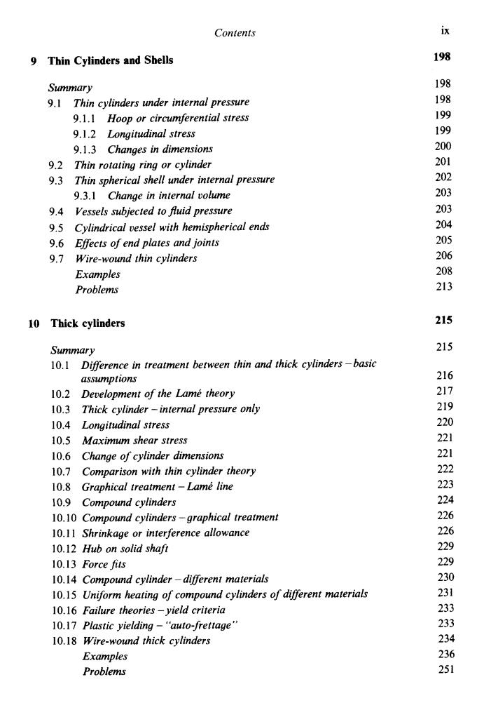
Contents ix 9 Thin Cylinders and Shells 198 Summary 198 9.1 Thin cylinders under internal pressure 198 9.1.1 Hoop or circumferential stress 199 9.1.2 Longitudinal stress 199 9.1.3 Changes in dimensions 200 9.2 Thin rotating ring or cylinder 201 9.3 Thin spherical shell under internal pressure 202 9.3.1 Change in internal volume 203 9.4 Vessels subjected to fluid pressure 203 9.5 Cylindrical vessel with hemispherical ends 204 9.6 Effects of end plates and joints 205 9.7 Wire-wound thin cylinders 206 Examples 208 Problems 213 10 Thick cylinders 215 Summary 215 10.1 Difference in treatment between thin and thick cylinders-basic assumptions 216 10.2 Development of the Lame theory 217 10.3 Thick cylinder -internal pressure only 219 10.4 Longitudinal stress 220 10.5 Maximum shear stress 221 10.6 Change of cylinder dimensions 221 10.7 Comparison with thin cylinder theory 222 10.8 Graphical treatment-Lame line 10.9 Compound cylinders 224 10.10 Compound cylinders-graphical treatment 10.11 Shrinkage or interference allowance 10.12 Hub on solid shaft 10.13 Force fits 229 10.14 Compound cylinder-different materials 10.15 Uniform heating of compound cylinders of different materials 231 10.16 Failure theories-yield criteria 233 10.17 Plastic yielding-"auto-frettage" 233 10.18 Wire-wound thick cylinders 234 Examples 236 Problems 251
Contents 9 Thin Cylinders and Shells ix 198 Summary 9.1 Thin cylinders under internal pressure 9.1.1 Hoop or circumferential stress 9.1.2 Longitudinal stress 9.1.3 Changes in dimensions Thin rotating ring or cylinder Thin spherical shell under internal pressure 9.3.1 Change in internal volume Vessels subjected to JIuid pressure Cylindrical vessel with hemispherical end Effects of end plates and joints Examples Problems 9.2 9.3 9.4 9.5 9.6 9.7 Wire-wound thin cylinders 10 Thick cylinders Summary 10.1 10.2 10.3 10.4 Longitudinal stress 10.5 Maximum shear stress 10.6 Change of cylinder dimensions 10.7 10.8 10.9 Compound cylinders 10.10 Compound cylinders -graphical treatment 10.1 1 Shrinkage or interference allowance 10.12 Hub on solid shaji 10.13 Force fits 10.14 Compound cylinder -different materials 10.15 Uniform heating of compound cylinders of different materials 10.16 Failure theories -yield criteria 10.17 Plastic yielding - “auto-frettage” 10.18 Wire-wound thick cylinders Difference in treatment between thin and thick cylinders -basic assumptions Development of the Lame theory Thick cylinder - internal pressure only Comparison with thin cylinder theory Graphical treatment - Lame line Examples Problems 198 198 199 199 200 20 1 202 203 203 204 205 206 208 213 215 215 216 217 219 220 22 1 22 1 222 223 224 226 226 229 229 230 23 1 233 233 234 236 25 1