CHAPTER 7 SHEAR STRESS DISTRIBUTION Summary The shear stress in a beam at any transverse cross-section in its length,and at a point a vertical distance y from the neutral axis,resulting from bending is given by Ib or t-Tb where o is the applied vertical shear force at that section;A is the area of cross-section "above"y,i.e.the area between y and the outside of the section,which may be above or below the neutral axis (N.A.);yis the distance of the centroid of area A from the N.A.;I is the second moment of area of the complete cross-section;and b is the breadth of the section at position y. For rectangular sections, 62「d2 30 with Imax=2bd when y=0 For I-section beams the vertical shear in the web is given by -小+[] with a maximum value of 器+[ The maximum value of the horizontal shear in the flanges is d-4 2b For circular sections =-(] with a maximum value of 40 tmax=3πR2 The shear centre of a section is that point,in or outside the section,through which load must be applied to produce zero twist of the section.Should a section have two axes of symmetry, the point where they cross is automatically the shear centre. 154
CHAPTER 7 SHEAR STRESS DISTRIBUTION Summary The shear stress in a beam at any transverse cross-section in its length, and at a point a vertical distance y from the neutral axis, resulting from bending is given by QAj 7=- Ib where Q is the applied vertical shear force at that section; A is the area of cross-section “above” y, i.e. the area between y and the outside of the section, which may be above or below the neutral axis (N.A.); jj is the distance of the centroid of area A from the N.A.; I is the second moment of area of the complete cross-section; and b is the breadth of the section at position y. For rectangular sections, 7=- :$[: -- y2] with 7,,=- 3Q when y =O 2bd For I-section beams the vertical shear in the web is given by with a maximum value of The maximum value of the horizontal shear in the flanges is For circular sections with a maximum value of 4Q T,, = __ 3aR2 The shear centre of a section is that point, in or outside the section, through which load must be applied to produce zero twist of the section. Should a section have two axes of symmetry, the point where they cross is automatically the shear centre. 154
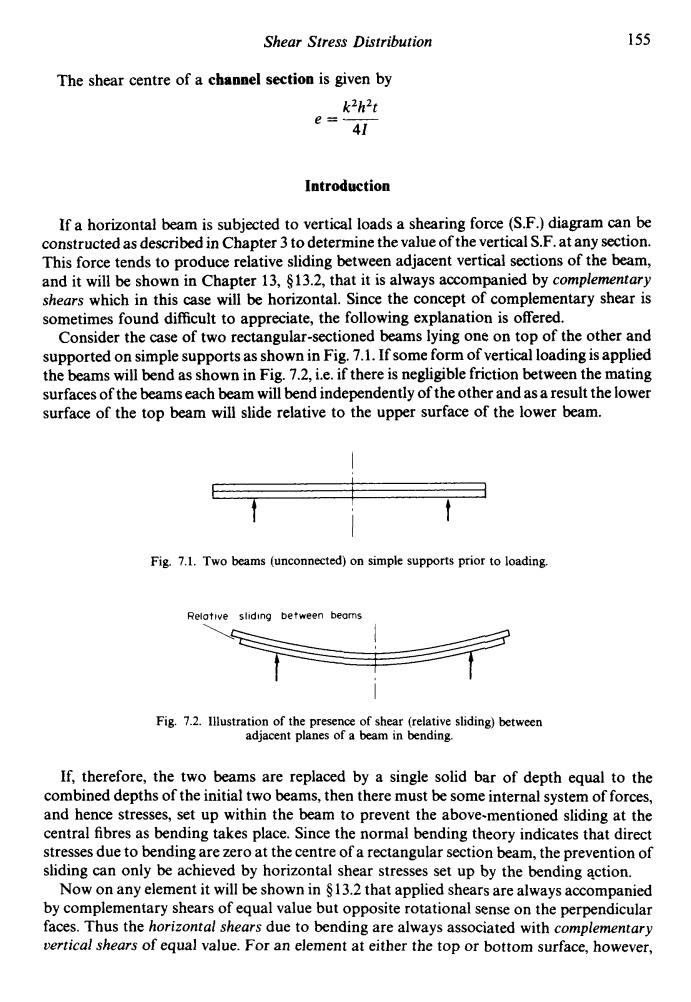
Shear Stress Distribution 155 The shear centre of a channel section is given by k2h2t e÷4l Introduction If a horizontal beam is subjected to vertical loads a shearing force (S.F.)diagram can be constructed as described in Chapter 3 to determine the value of the vertical S.F.at any section. This force tends to produce relative sliding between adjacent vertical sections of the beam, and it will be shown in Chapter 13,$13.2,that it is always accompanied by complementary shears which in this case will be horizontal.Since the concept of complementary shear is sometimes found difficult to appreciate,the following explanation is offered. Consider the case of two rectangular-sectioned beams lying one on top of the other and supported on simple supports as shown in Fig.7.1.If some form of vertical loading is applied the beams will bend as shown in Fig.7.2,i.e.if there is negligible friction between the mating surfaces of the beams each beam will bend independently of the other and as a result the lower surface of the top beam will slide relative to the upper surface of the lower beam. Fig.7.1.Two beams (unconnected)on simple supports prior to loading. Relotive sliding between beams Fig.7.2.Illustration of the presence of shear(relative sliding)between adjacent planes of a beam in bending. If,therefore,the two beams are replaced by a single solid bar of depth equal to the combined depths of the initial two beams,then there must be some internal system of forces, and hence stresses,set up within the beam to prevent the above-mentioned sliding at the central fibres as bending takes place.Since the normal bending theory indicates that direct stresses due to bending are zero at the centre of a rectangular section beam,the prevention of sliding can only be achieved by horizontal shear stresses set up by the bending action. Now on any element it will be shown in $13.2 that applied shears are always accompanied by complementary shears of equal value but opposite rotational sense on the perpendicular faces.Thus the horizontal shears due to bending are always associated with complementary vertical shears of equal value.For an element at either the top or bottom surface,however
Shear Stress Distribution 155 The shear centre of a channel section is given by kZhZt e=- 41 Introduction If a horizontal beam is subjected to vertical loads a shearing force (S.F.) diagram can be constructed as described in Chapter 3 to determine the value of the vertical S.F. at any section. This force tends to produce relative sliding between adjacent vertical sections of the beam, and it will be shown in Chapter 13, 513.2, that it is always accompanied by complementary shears which in this case will be horizontal. Since the concept of complementary shear is sometimes found difficult to appreciate, the following explanation is offered. Consider the case of two rectangular-sectioned beams lying one on top of the other and supported on simple supports as shown in Fig. 7.1. If some form of vertical loading is applied the beams will bend as shown in Fig. 7.2, i.e. if there is neghgible friction between the mating surfaces of the beams each beam will bend independently of the other and as a result the lower surface of the top beam will slide relative to the upper surface of the lower beam. Fig. 7.1. Two beams (unconnected) on simple supports prior to loading. Relative sliding between beams Fig. 7.2. Illustration of the presence of shear (relative sliding) between adjacent planes of a beam in bending. If, therefore, the two beams are replaced by a single solid bar of depth equal to the combined depths of the initial two beams, then there must be some internal system of forces, and hence stresses, set up within the beam to prevent the above-mentioned sliding at the central fibres as bending takes place. Since the normal bending theory indicates that direct stresses due to bending are zero at the centre of a rectangular section beam, the prevention of sliding can only be achieved by horizontal shear stresses set up by the bending action. Now on any element it will be shown in 5 13.2 that applied shears are always accompanied by complementary shears of equal value but opposite rotational sense on the perpendicular faces. Thus the horizontal shears due to bending are always associated with complementary vertical shears of equal value. For an element at either the top or bottom surface, however
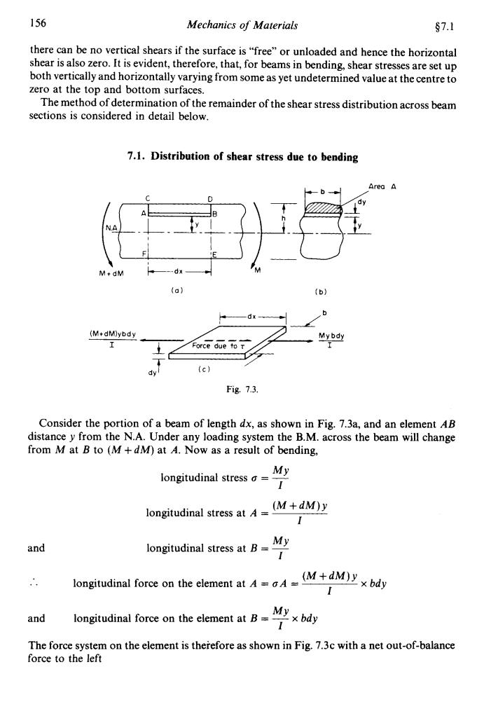
156 Mechanics of Materials 67.1 there can be no vertical shears if the surface is "free"or unloaded and hence the horizontal shear is also zero.It is evident,therefore,that,for beams in bending,shear stresses are set up both vertically and horizontally varying from some as yet undetermined value at the centre to zero at the top and bottom surfaces. The method of determination of the remainder of the shear stress distribution across beam sections is considered in detail below. 7.1.Distribution of shear stress due to bending Area A NA M+dM -dx (a) (b》 (M+dM)ybdy My bdy Force due to r dy (c) Fig.7.3. Consider the portion of a beam of length dx,as shown in Fig.7.3a,and an element AB distance y from the N.A.Under any loading system the B.M.across the beam will change from M at B to (M+dM)at A.Now as a result of bending, longitudinal stress a= My 1 longitudinal stress at=(M+dM)y 1 and longitudinal stress at B-My longitudinal force on the element atMM)by My and longitudinal force on the element at B= x bdy The force system on the element is therefore as shown in Fig.7.3c with a net out-of-balance force to the left
156 Mechanics of Materials $7.1 there can be no vertical shears if the surface is "free" or unloaded and hence the horizontal shear is also zero. It is evident, therefore, that, for beams in bending, shear stresses are set up both vertically and horizontally varying from some as yet undetermined value at the centre to zero at the top and bottom surfaces. The method of determination of the remainder of the shear stress distribution across beam sections is considered in detail below. 7.1. Distribution of shear stress due to bending C D // I I (Mt dM)ybd y I 1 I Fig. 1.3. Consider the portion of a beam of length dx, as shown in Fig. 7.3a, and an element AB distance y from the N.A. Under any loading system the B.M. across the beam will change from M at B to (A4 + dM) at A. Now as a result of bending, and .. longituLinr MY longitudinal stress o = - (M+dWY MY longitudinal stress at B = ~ I I longitudinal stress at A = I x ". (M+dWY I rce on the element at A = oA = Y MY and The force system on the element is therefore as shown in Fig. 7.3~ with a net out-of-balance force to the left longitudinal force on the element at B = - x bdy I
§7.2 Shear Stress Distribution 157 (d +M)ndy ndy 1 dM 起了bdy Therefore total out-of-balance force from all sections above height y h [am For equilibrium,this force is resisted by a shear force set up on the section of length dx and breadth b,as shown in Fig.7.4. h aM ybdy Fig.7.4. Thus if the shear stress is t,then dM ybdy (7.10 h But ybdy first moment of area of shaded portion of Fig.7.3b about the N.A. =A5 where A is the area of shaded portion and y the distance of its centroid from the N.A. dM Also rate of change of the B.M. =S.F.O at the section t=24y Ib (7.2) or,alternatively, ydA where dA =bdy (7.3) 7.2.Application to rectangular sections Consider now the rectangular-sectioned beam of Fig.7.5 subjected at a given transverse cross-section to a S.F.O
$7.2 Shear Stress Distribution 157 Therefore total out-of-balance force from all sections above height y = jgybdy I Y For equilibrium, this force is resisted by a shear force set up on the section of length dx and breadth b, as shown in Fig. 7.4. h C D [ ybdy Y Fig. 7.4. Thus if the shear stress is T, then h But j ybdy = first moment of area of shaded iortion of Fig. 7.3b about the N.A. Y = Aj where A is the area of shaded portion and j the distance of its centroid from the N.A. dM ~ = rate of change of the B.M. dx Also = S.F. Q at the section .. QAY z=- lb or, alternatively, z = 2 ydA where dA = bdy lb Y 7.2. Application to rectangular sections Consider now the rectangular-sectioned beam of Fig. 7.5 subjected at a given transverse cross-section to a S.F. Q
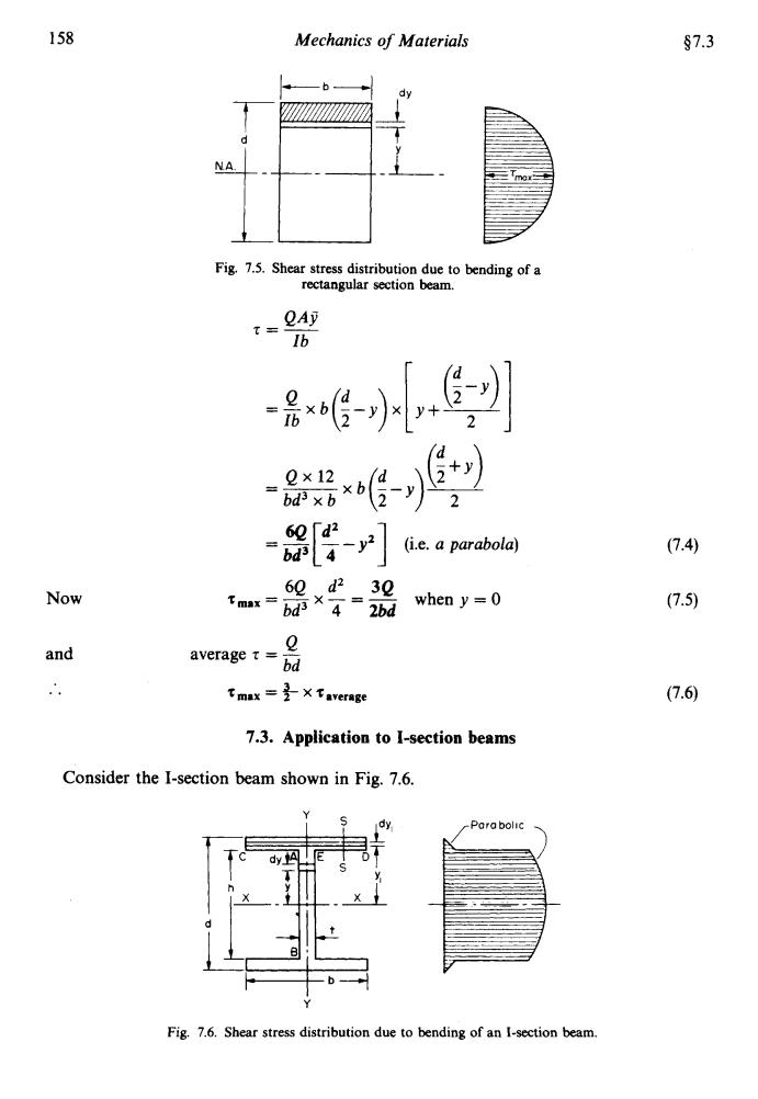
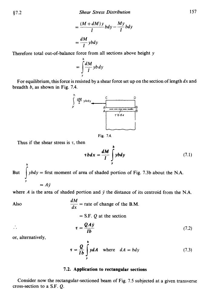
158 Mechanics of Materials §7.3 NA Fig.7.5.Shear stress distribution due to bending of a rectangular section beam. Ib 8哈是到 -0 2×122 60「d2 -04 (i.e.a parabola) (7.40 Now 60、d230 Tmx=6dX4= 2bd when y=0 (7.5) and average t bd tmax=是X Taverage (7.6) 7.3.Application to I-section beams Consider the I-section beam shown in Fig.7.6. Para bolic dy Fig.7.6.Shear stress distribution due to bending of an I-section beam
158 Mechanics of Materials $7.3 Now and .. Fig. 7.5. Shear stress distribution due to bending of a rectangular section beam. = 6Q d2 [T - y2] (i.e. a parabola) 6Q d2 3Q bd3 4 2bd TmaX = - x - = - when y = 0 Q average z = - bd % max = t x %average 7.3. Application to I-section beams Consider the I-section beam shown in Fig. 7.6. ,Porobolic , Y Fig. 7.6. Shear stress distribution due to bending of an I-section beam