11/35 9.1 Time,Frequency,and Phase-Angle Measurement Analysis of the trigger error gives the standard deviation of the timing error as: rms trigger error N+N+N+N (9.2) Where Nc:counter noise,V rms(typically 0.2 to 2.0 mV) No:start-signal noise,V rms N:stop-signal noise,V rms a:slew rate(变化率)of start signal at trigger(触发)point,V小s V:slew rate of start signal at trigger point,V/s 2/35 9.1 Time,Frequency,and Phase-Angle Measurement eole;=0 0360° 90°270° E;sin wt E。sin(wt+φ) +180°,-180° Fig.9.3(a)Phase Angle from Lissajous Figure(利萨如图形) Another common method of phase-angle measurement involves cross-plotting the two sinusoidal signals against each other,by using an XY plotter for very low frequencies and an oscilloscope for high frequencies.The cross plot can be shown to be an ellipse,and suitable measurement on this ellipse give the phase angle
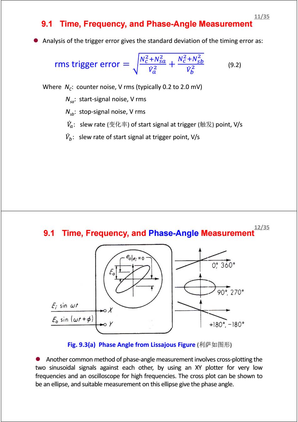
9.1 Time, Frequency, and Phase-Angle Measurement z Analysis of the trigger error gives the standard deviation of the timing error as: rms trigger error ே మାேೞೌ మ ሶ ೌ మ ே మାேೞ್ మ ሶ ್ మ (9.2) Where NC: counter noise, V rms (typically 0.2 to 2.0 mV) Nsa: start-signal noise, V rms Nsb: stop-signal noise, V rms ܸሶ : slew rate (变化率) of start signal at trigger (触发) point, V/s ܸሶ : slew rate of start signal at trigger point, V/s 11/35 Fig. 9.3(a) Phase Angle from Lissajous Figure (利萨如图形) z Another common method of phase-angle measurement involves cross-plotting the two sinusoidal signals against each other, by using an XY plotter for very low frequencies and an oscilloscope for high frequencies. The cross plot can be shown to be an ellipse, and suitable measurement on this ellipse give the phase angle. 9.1 Time, Frequency, and Phase-Angle Measurement12/35
3/35 9.1 Time,Frequency,and Phase-Angle Measurement Ei sin wt E。sin(wt+p 11N11113s1901t11共11/ 180 0 Fosin wt Calibrated phase-shift device Figure 9.3b Phase Angle from Lissajous Figure-Straight line An alternative method employing the same basic principle but a null technique. The calibrated phase-shift circuit is adjusted until the ellipse degenerates into a straight line.Then the phase angle is read directly from the phase-shifter dial. When the "sinusoidal"signal are noisy and/or distorted,special phase meters and tracking filters may be necessary for accurate measurement. 14/35 9.2 Liquid Level Using Motion Force Tx Measurement and/or control of liquid level in tanks is an important function in many industrial processes and in more exotic()applications, such as the operation and fueling of large liquid-fuel rocket motors. Motion Force transducer transducer (o) (61 Figure 9.4 Liquid Level Measurement Strategies -Fig.9.4(a):a simple float is coupled to some suitable motion transducer to produce an electrical signal proportional to the liquid level. -Fig.9.4(b):a displacer which has negligible motion and measures the liquid level in terms of buoyant force by means of a force transducer
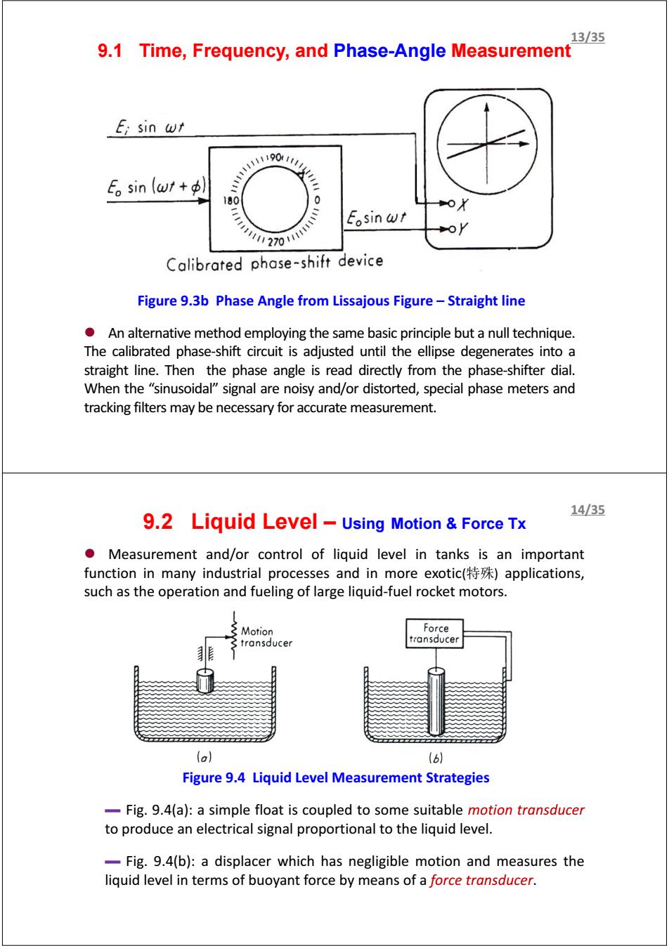
Figure 9.3b Phase Angle from Lissajous Figure – Straight line z An alternative method employing the same basic principle but a null technique. The calibrated phase-shift circuit is adjusted until the ellipse degenerates into a straight line. Then the phase angle is read directly from the phase-shifter dial. When the “sinusoidal” signal are noisy and/or distorted, special phase meters and tracking filters may be necessary for accurate measurement. 9.1 Time, Frequency, and Phase-Angle Measurement 13/35 z Measurement and/or control of liquid level in tanks is an important function in many industrial processes and in more exotic(特殊) applications, such as the operation and fueling of large liquid-fuel rocket motors. 9.2 Liquid Level – Using Motion & Force Tx Figure 9.4 Liquid Level Measurement Strategies ▬ Fig. 9.4(a): a simple float is coupled to some suitable motion transducer to produce an electrical signal proportional to the liquid level. ▬ Fig. 9.4(b): a displacer which has negligible motion and measures the liquid level in terms of buoyant force by means of a force transducer. 14/35