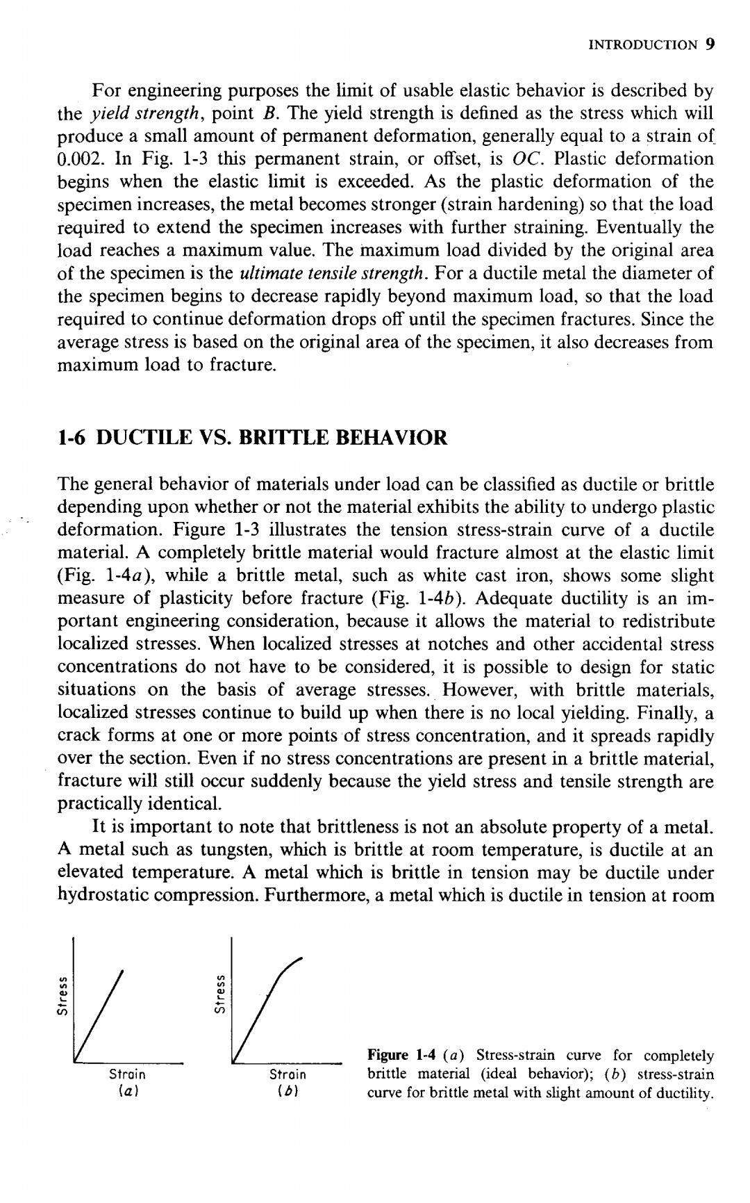
INTRODUCTION 9 For engineering purposes the limit of usable elastic behavior is described by the yield strength,point B.The yield strength is defined as the stress which will produce a small amount of permanent deformation,generally equal to a strain of 0.002.In Fig.1-3 this permanent strain,or offset,is OC.Plastic deformation begins when the elastic limit is exceeded.As the plastic deformation of the specimen increases,the metal becomes stronger(strain hardening)so that the load required to extend the specimen increases with further straining.Eventually the load reaches a maximum value.The maximum load divided by the original area of the specimen is the ultimate tensile strength.For a ductile metal the diameter of the specimen begins to decrease rapidly beyond maximum load,so that the load required to continue deformation drops off until the specimen fractures.Since the average stress is based on the original area of the specimen,it also decreases from maximum load to fracture. 1-6 DUCTILE VS.BRITTLE BEHAVIOR The general behavior of materials under load can be classified as ductile or brittle depending upon whether or not the material exhibits the ability to undergo plastic deformation.Figure 1-3 illustrates the tension stress-strain curve of a ductile material.A completely brittle material would fracture almost at the elastic limit (Fig.1-4a),while a brittle metal,such as white cast iron,shows some slight measure of plasticity before fracture (Fig.1-4b).Adequate ductility is an im- portant engineering consideration,because it allows the material to redistribute localized stresses.When localized stresses at notches and other accidental stress concentrations do not have to be considered,it is possible to design for static situations on the basis of average stresses.However,with brittle materials, localized stresses continue to build up when there is no local yielding.Finally,a crack forms at one or more points of stress concentration,and it spreads rapidly over the section.Even if no stress concentrations are present in a brittle material, fracture will still occur suddenly because the yield stress and tensile strength are practically identical. It is important to note that brittleness is not an absolute property of a metal. A metal such as tungsten,which is brittle at room temperature,is ductile at an elevated temperature.A metal which is brittle in tension may be ductile under hydrostatic compression.Furthermore,a metal which is ductile in tension at room n Figure 1-4 (a)Stress-strain curve for completely Strain Stroin brittle material (ideal behavior);(b)stress-strain (a) (b} curve for brittle metal with slight amount of ductility
10 MECHANICAL FUNDAMENTALS temperature can become brittle in the presence of notches,low temperature,high rates of loading,or embrittling agents such as hydrogen. 1-7 WHAT CONSTITUTES FAILURE? Structural members and machine elements can fail to perform their intended functions in three general ways: 1.Excessive elastic deformation 2.Yielding,or excessive plastic deformation 3.Fracture An understanding of the common types of failure is important in good design because it is always necessary to relate the loads and dimensions of the member to some significant material parameter which limits the load-carrying capacity of the member.For different types of failure,different significant parameters will be important. Two general types of excessive elastic deformation may occur:(1)excessive deflection under condition of stable equilibrium,such as the deflection of beam under gradually applied loads;(2)sudden deflection,or buckling,under condi- tions of unstable equilibrium. Excessive elastic deformation of a machine part can mean failure of the machine just as much as if the part completely fractured.For example,a shaft which is too flexible can cause rapid wear of the bearing,or the excessive deflection of closely mating parts can result in interference and damage to the parts.The sudden buckling type of failure may occur in a slender column when the axial load exceeds the Euler critical load or when the external pressure acting against a thin-walled shell exceeds a critical value.Failures due to excessive elastic deformation are controlled by the modulus of elasticity,not by the strength of the material.Generally,little metallurgical control can be exercised over the elastic modulus.The most effective way to increase the stiffness of a member is usually by changing its shape and increasing the dimensions of its cross section. Yielding,or excessive plastic deformation,occurs when the elastic limit of the metal has been exceeded.Yielding produces permanent change of shape,which may prevent the part from functioning properly any longer.In a ductile metal under conditions of static loading at room temperature yielding rarely results in fracture,because the metal strain hardens as it deforms,and an increased stress is required to produce further deformation.Failure by excessive plastic deformation is controlled by the yield strength of the metal for a uniaxial condition of loading. For more complex loading conditions the yield strength is still the significant parameter,but it must be used with a suitable failure criterion (Sec.3-4).At temperatures significantly greater than room temperature metals no longer exhibit strain hardening.Instead,metals can continuously deform at constant stress in a time-dependent yielding known as creep.The failure criterion under creep condi-
INTRODUCTION 11 tions is complicated by the fact that stress is not proportional to strain and the further fact that the mechanical properties of the material may change apprecia- bly during service.This complex phenomenon will be considered in greater detail in Chap.13. The formation of a crack which can result in complete disruption of continu- ity of the member constitutes fracture.A part made from a ductile metal which is loaded statically rarely fractures like a tensile specimen,because it will first fail by excessive plastic deformation.However,metals fail by fracture in three general ways:(1)sudden brittle fracture;(2)fatigue,or progressive fracture;(3)delayed fracture.In the previous section it was shown that a brittle material fractures under static loads with little outward evidence of yielding.A sudden brittle type of fracture can also occur in ordinarily ductile metals under certain conditions. Plain carbon structural steel is the most common example of a material with a ductile-to-brittle transition.A change from the ductile to the brittle type of fracture is promoted by a decrease in temperature,an increase in the rate of loading,and the presence of a complex state of stress due to a notch.This problem is considered in Chap.14.A powerful and quite general method of analysis for brittle fracture problems is the technique called fracture mechanics. This is treated in detail in Chap.11. Most fractures in machine parts are due to fatigue.Fatigue failures occur in parts which are subjected to alternating,or fluctuating,stresses.A minute crack starts at a localized spot,generally at a notch or stress concentration,and gradually spreads over the cross section until the member breaks.Fatigue failure occurs without any visible sign of yielding at nominal or average stresses that are well below the tensile strength of the metal.Fatigue failure is caused by a critical localized tensile stress which is very difficult to evaluate,and therefore design for fatigue failure is based primarily on empirical relationships using nominal stresses. Fatigue of metals is discussed in greater detail in Chap.12. One common type of delayed fracture is stress-rupture failure,which occurs when a metal has been statically loaded at an elevated temperature for a long period of time.Depending upon the stress and the temperature there may be no yielding prior to fracture.A similar type of delayed fracture,in which there is no warning by yielding prior to failure,occurs at room temperature when steel is statically loaded in the presence of hydrogen. All engineering materials show a certain variability in mechanical properties, which in turn can be influenced by changes in heat treatment or fabrication. Further,uncertainties usually exist regarding the magnitude of the applied loads, and approximations are usually necessary in calculating stresses for all but the most simple member.Allowance must be made for the possibility of accidental loads of high magnitude.Thus,in order to provide a margin of safety and to protect against failure from unpredictable causes,it is necessary that the allow- able stresses be smaller than the stresses which produce failure.The value of stress for a particular material used in a particular way which is considered to be a safe stress is usually called the working stress o.For static applications the working stress of ductile metals is usually based on the yield strength oo and for brittle
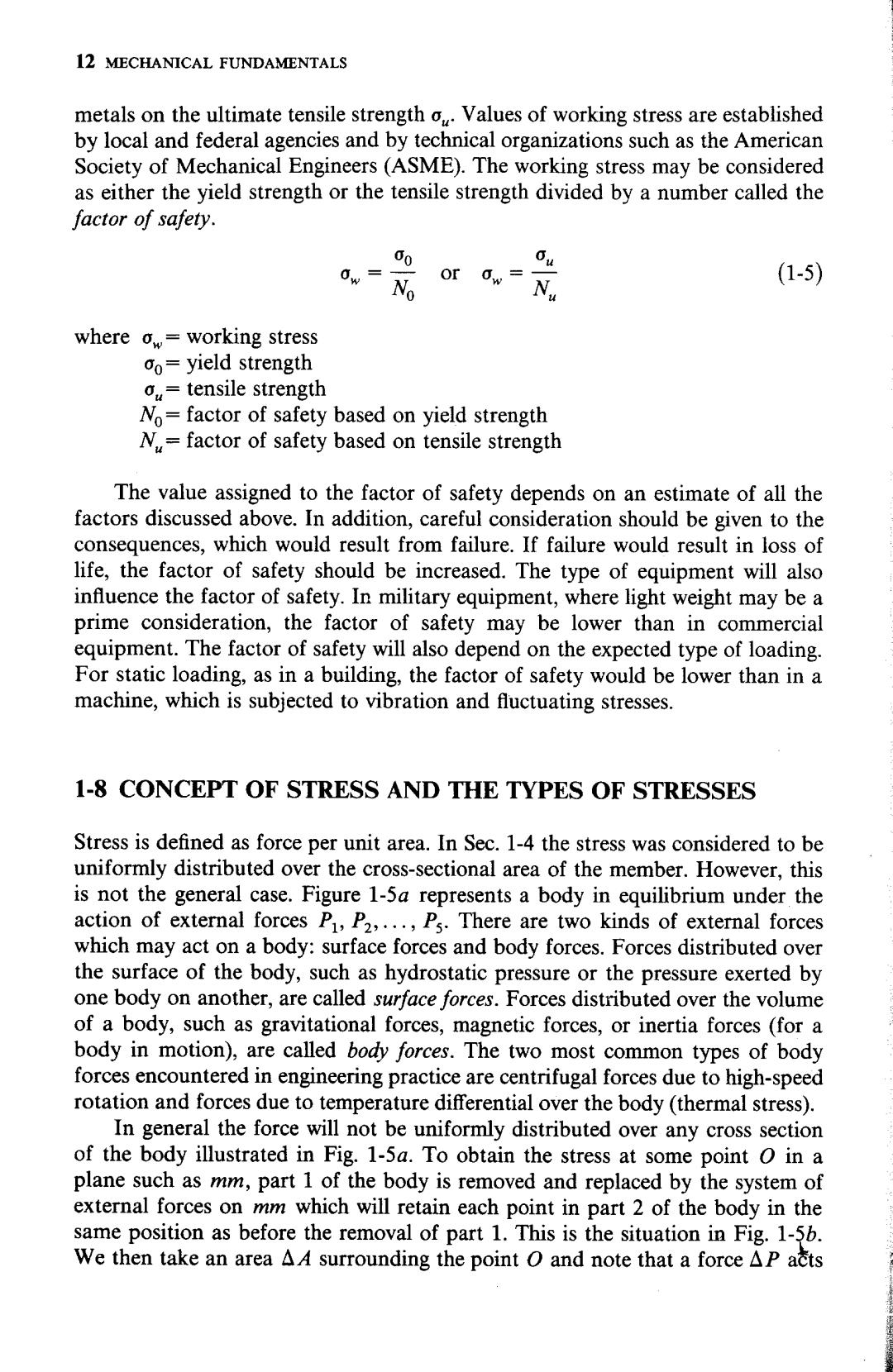
12 MECHANICAL FUNDAMENTALS metals on the ultimate tensile strength o,.Values of working stress are established by local and federal agencies and by technical organizations such as the American Society of Mechanical Engineers (ASME).The working stress may be considered as either the yield strength or the tensile strength divided by a number called the factor of safety. 0 Ou 0w= No or w= Nu (1-5) where ow=working stress co=yield strength o.=tensile strength No=factor of safety based on yield strength N,factor of safety based on tensile strength The value assigned to the factor of safety depends on an estimate of all the factors discussed above.In addition,careful consideration should be given to the consequences,which would result from failure.If failure would result in loss of life,the factor of safety should be increased.The type of equipment will also influence the factor of safety.In military equipment,where light weight may be a prime consideration,the factor of safety may be lower than in commercial equipment.The factor of safety will also depend on the expected type of loading. For static loading,as in a building,the factor of safety would be lower than in a machine,which is subjected to vibration and fluctuating stresses. 1-8 CONCEPT OF STRESS AND THE TYPES OF STRESSES Stress is defined as force per unit area.In Sec.1-4 the stress was considered to be uniformly distributed over the cross-sectional area of the member.However,this is not the general case.Figure 1-5a represents a body in equilibrium under the action of external forces P,P2,...,P3.There are two kinds of external forces which may act on a body:surface forces and body forces.Forces distributed over the surface of the body,such as hydrostatic pressure or the pressure exerted by one body on another,are called surface forces.Forces distributed over the volume of a body,such as gravitational forces,magnetic forces,or inertia forces (for a body in motion),are called body forces.The two most common types of body forces encountered in engineering practice are centrifugal forces due to high-speed rotation and forces due to temperature differential over the body(thermal stress). In general the force will not be uniformly distributed over any cross section of the body illustrated in Fig.1-5a.To obtain the stress at some point o in a plane such as mm,part 1 of the body is removed and replaced by the system of external forces on mm which will retain each point in part 2 of the body in the same position as before the removal of part 1.This is the situation in Fig.1-5b. We then take an area aA surrounding the point O and note that a force ap acts
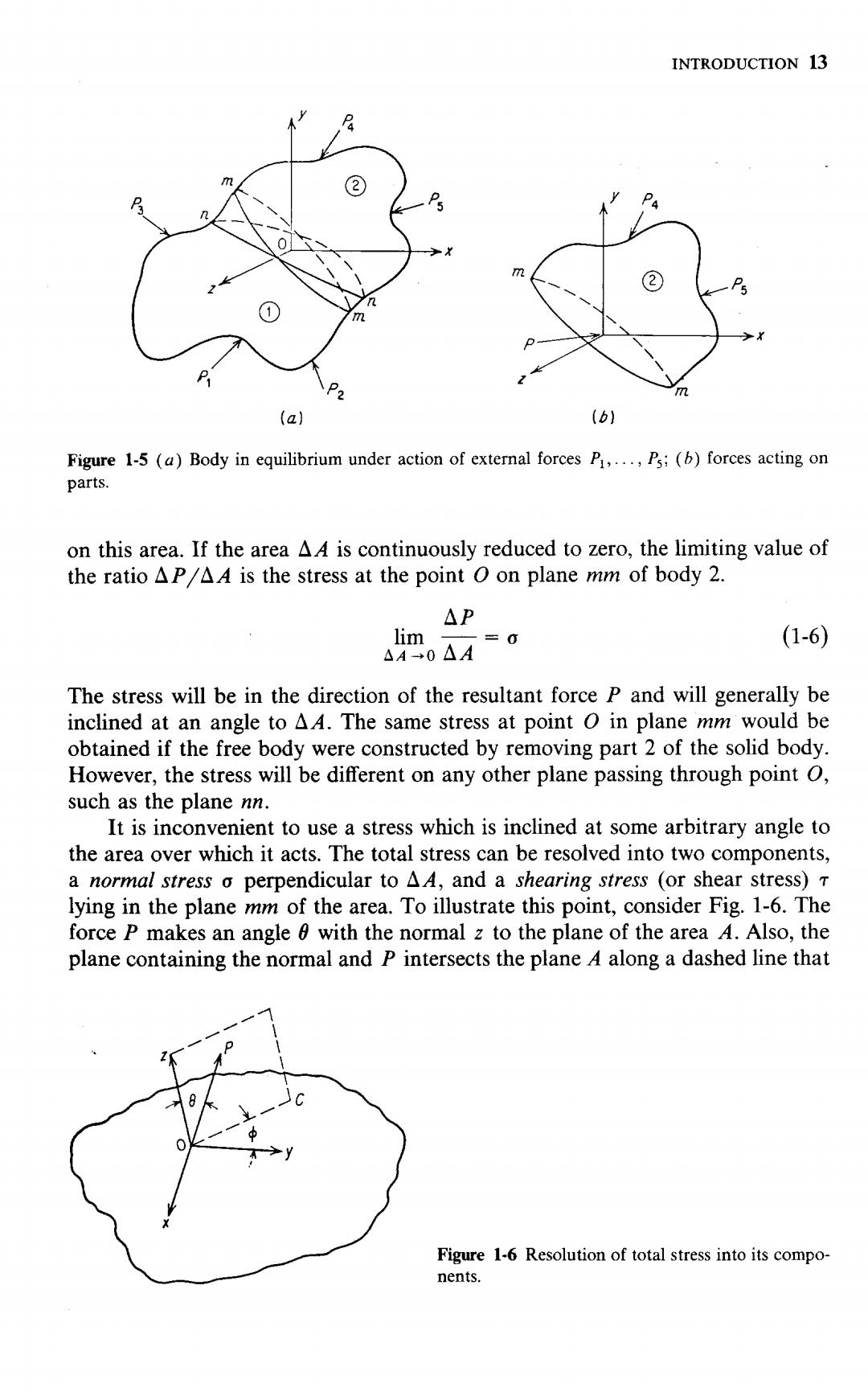
INTRODUCTION 13 ② P5 m 2 1 P2 (a) (b) Figure 1-5 (a)Body in equilibrium under action of external forces P,...,P5;(b)forces acting on parts. on this area.If the area Ad is continuously reduced to zero,the limiting value of the ratio aP Ad is the stress at the point O on plane mm of body 2. △P lim =0 (1-6) AA-0△A The stress will be in the direction of the resultant force P and will generally be inclined at an angle to AA.The same stress at point o in plane mm would be obtained if the free body were constructed by removing part 2 of the solid body. However,the stress will be different on any other plane passing through point O, such as the plane nn. It is inconvenient to use a stress which is inclined at some arbitrary angle to the area over which it acts.The total stress can be resolved into two components, a normal stress o perpendicular to AA,and a shearing stress (or shear stress)T lying in the plane mm of the area.To illustrate this point,consider Fig.1-6.The force P makes an angle with the normal z to the plane of the area A.Also,the plane containing the normal and P intersects the plane A along a dashed line that Figure 1-6 Resolution of total stress into its compo- nents