4 MECHANICAL FUNDAMENTALS worth spending the time to become familiar with the mathematics presented in Part One. The theories of strength of materials,elasticity,and plasticity lose much of their power when the structure of the metal becomes an important consideration and it can no longer be considered a homogeneous medium.Examples of this are in the high-temperature behavior of metals,where the metallurgical structure may continuously change with time,or in the ductile-to-brittle transition,which occurs in carbon steel.The determination of the relationship between mechanical behav- ior and structure (as detected chiefly with microscopic and x-ray techniques)is the main responsibility of the mechanical metallurgist.When mechanical behavior is understood in terms of metallurgical structure,it is generally possible to improve the mechanical properties or at least to control them.Part Two of this book is concerned with the metallurgical fundamentals of the mechanical behavior of metals.Metallurgical students will find that some of the material in Part Two has been covered in a previous course in physical metallurgy,since mechanical metallurgy is part of the broader field of physical metallurgy.However,these subjects are considered in greater detail than is usually the case in a first course in physical metallurgy.In addition,certain topics which pertain more to physical metallurgy than mechanical metallurgy have been included in order to provide continuity and to assist nonmetallurgical students who may not have had a course in physical metallurgy. The last three chapters of Part Two are concerned primarily with atomistic concepts of the flow and fracture of metals.Many of the developments in these areas have been the result of the alliance of the solid-state physicist with the metallurgist.This has been an area of great progress.The introduction of transmission electron microscopy has provided an important experimental tool for verifying theory and guiding analysis.A body of basic dislocation theory is presented which is useful for understanding the mechanical behavior of crystalline solids. Basic data concerning the strength of metals and measurements for the routine control of mechanical properties are obtained from a relatively small number of standardized mechanical tests.Part Three,Applications to Materials Testing,considers each of the common mechanical tests,not from the usual standpoint of testing techniques,but instead from the consideration of what these tests tell about the service performance of metals and how metallurgical variables affect the results of these tests.Much of the material in Parts One and Two has been utilized in Part Three.It is assumed that the reader either has completed a conventional course in materials testing or will be concurrently taking a labora- tory course in which familiarization with the testing techniques will be acquired. Part Four considers the metallurgical and mechanical factors involved in forming metals into useful shapes.Attempts have been made to present mathe- matical analyses of the principal metalworking processes,although in certain cases this has not been possible,either because of the considerable detail required or because the analysis is beyond the scope of this book.No attempt has been made to include the extensive specialized technology associated with each metal-

INTRODUCTION 5 working process,such as rolling or extrusion,although some effort has been made to give a general impression of the mechanical equipment required and to familiarize the reader with the specialized vocabulary of the metalworking field. Major emphasis has been placed on presenting a fairly simplified picture of the forces involved in each process and of how geometrical and metallurgical factors affect the forming loads and the success of the metalworking process. 1-2 STRENGTH OF MATERIALS-BASIC ASSUMPTIONS Strength of materials is the body of knowledge which deals with the relation between internal forces,deformation,and external loads.In the general method of analysis used in strength of materials the first step is to assume that the member is in equilibrium.The equations of static equilibrium are applied to the forces acting on some part of the body in order to obtain a relationship between the external forces acting on the member and the internal forces resisting the action of the external loads.Since the equations of equilibrium must be expressed in terms of forces acting external to the body,it is necessary to make the internal resisting forces into external forces.This is done by passing a plane through the body at the point of interest.The part of the body lying on one side of the cutting plane is removed and replaced by the forces it exerted on the cut section of the part of the body that remains.Since the forces acting on the "free body"hold it in equilibrium,the equations of equilibrium may be applied to the problem. The internal resisting forces are usually expressed by the stress'acting over a certain area,so that the internal force is the integral of the stress times the differential area over which it acts.In order to evaluate this integral,it is necessary to know the distribution of the stress over the area of the cutting plane. The stress distribution is arrived at by observing and measuring the strain distribution in the member,since stress cannot be physically measured.However, since stress is proportional to strain for the small deformations involved in most work,the determination of the strain distribution provides the stress distribution. The expression for the stress is then substituted into the equations of equilibrium, and they are solved for stress in terms of the loads and dimensions of the member. Important assumptions in strength of materials are that the body which is being analyzed is continuous,homogeneous,and isotropic.A continuous body is one which does not contain voids or empty spaces of any kind.A body is homogeneous if it has identical properties at all points.A body is considered to be isotropic with respect to some property when that property does not vary with direction or orientation.A property which varies with orientation with respect to some system of axes is said to be anisotropic. 1For present purposes stress is defined as force per unit area.The companion term sirain is defined as the change in length per unit length.More complete definitions will be given later
6 MECHANICAL FUNDAMENTALS While engineering materials such as steel,cast iron,and aluminum may appear to meet these conditions when viewed on a gross scale,it is readily apparent when they are viewed through a microscope that they are anything but homogeneous and isotropic.Most engineering metals are made up of more than one phase,with different mechanical properties,such that on a micro scale they are heterogeneous.Further,even a single-phase metal will usually exhibit chem- ical segregation,and therefore the properties will not be identical from point to point.Metals are made up of an aggregate of crystal grains having different properties in different crystallographic directions.The reason why the equations of strength of materials describe the behavior of real metals is that,in general,the crystal grains are so small that,for a specimen of any macroscopic volume,the materials are statistically homogeneous and isotropic.However,when metals are severely deformed in a particular direction,as in rolling or forging,the mechani- cal properties may be anisotropic on a macro scale.Other examples of anisotropic properties are fiber-reinforced composite materials and single crystals.Lack of continuity may be present in porous castings or powder metallurgy parts and,on an atomic level,at defects such as vacancies and dislocations. 1-3 ELASTIC AND PLASTIC BEHAVIOR Experience shows that all solid materials can be deformed when subjected to external load.It is further found that up to certain limiting loads a solid will recover its original dimensions when the load is removed.The recovery of the original dimensions of a deformed body when the load is removed is known as elastic behavior.The limiting load beyond which the material no longer behaves elastically is the elastic limit.If the elastic limit is exceeded,the body will experience a permanent set or deformation when the load is removed.A body which is permanently deformed is said to have undergone plastic deformation. For most materials,as long as the load does not exceed the elastic limit,the deformation is proportional to the load.This relationship is known as Hooke's law;it is more frequently stated as stress is proportional to strain.Hooke's law requires that the load-deformation relationship should be linear.However,it does not necessarily follow that all materials which behave elastically will have a linear stress-strain relationship.Rubber is an example of a material with a nonlinear stress-strain relationship that still satisfies the definition of an elastic material. Elastic deformations in metals are quite small and require very sensitive instruments for their measurement.Ultrasensitive instruments have shown that the elastic limits of metals are much lower than the values usually measured in engineering tests of materials.As the measuring devices become more sensitive, the elastic limit is decreased,so that for most metals there is only a rather narrow range of loads over which Hooke's law strictly applies.This is,however,primarily of academic importance.Hooke's law remains a quite valid relationship for engineering design
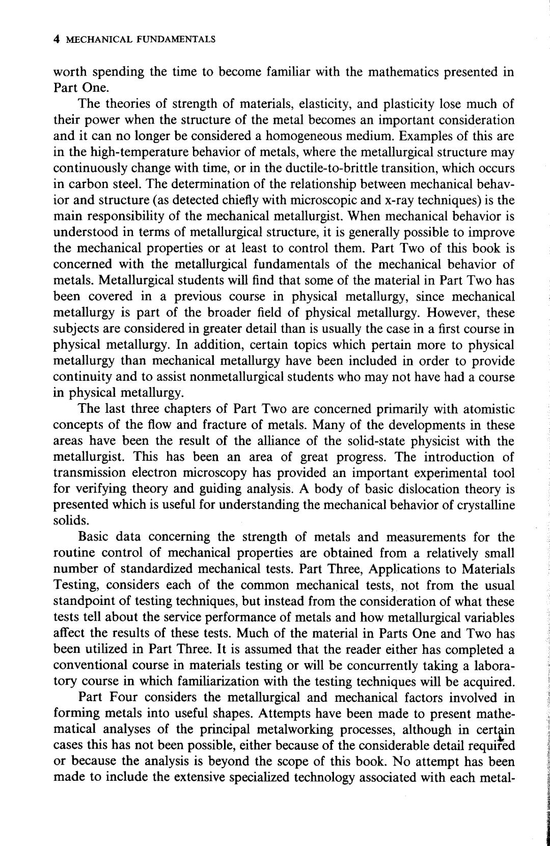
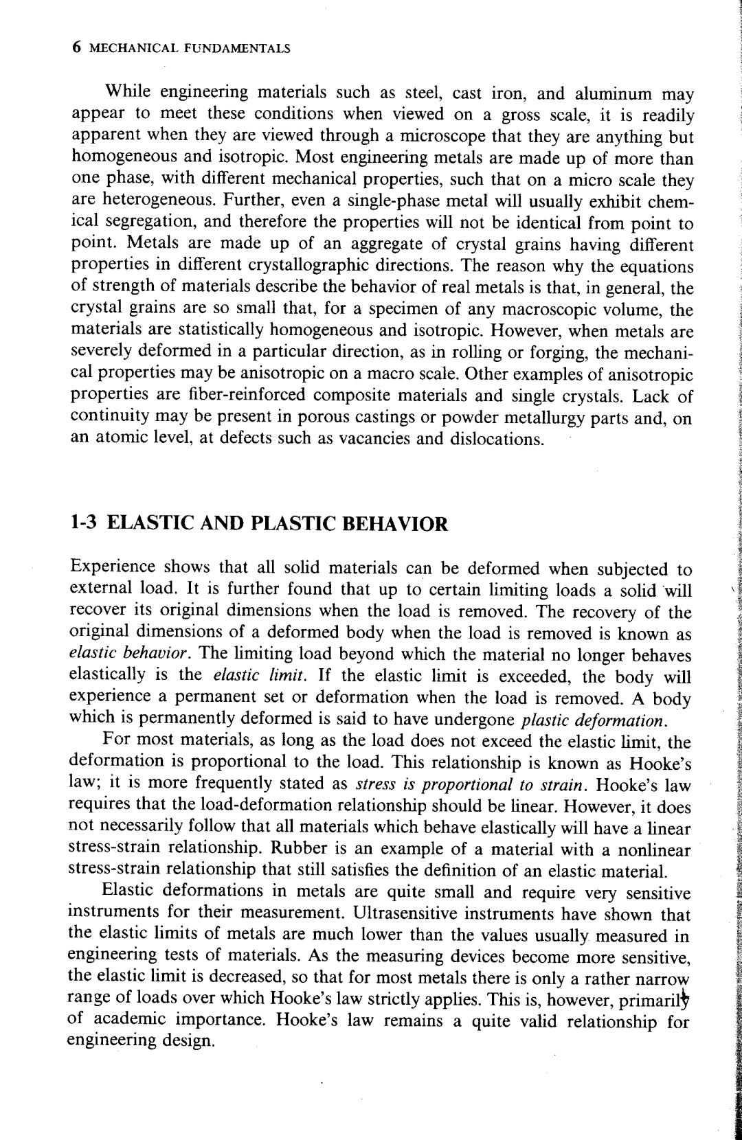
INTRODUCTION 7 Lo+8 Figure 1-1 Cylindrical bar subjected to axial load. Figure 1-2 Free-body diagram for Fig.1-1. 1-4 AVERAGE STRESS AND STRAIN As a starting point in the discussion of stress and strain,consider a uniform cylindrical bar which is subjected to an axial tensile load(Fig.1-1).Assume that two gage marks are put on the surface of the bar in its unstrained state and that Lo is the gage length between these marks.A load p is applied to one end of the bar,and the gage length undergoes a slight increase in length and decrease in diameter.The distance between the gage marks has increased by an amount 6, called the deformation.The average linear strain e is the ratio of the change in length to the original length. 8△LL-Lo e= LoLo Lo (1-1) Strain is a dimensionless quantity since both 8 and Lo are expressed in units of length. Figure 1-2 shows the free-body diagram for the cylindrical bar shown in Fig. 1-1.The external load P is balanced by the internal resisting force fo d4,where o is the stress normal to the cutting plane and A is the cross-sectional area of the bar.The equilibrium equation is P=odA (1-2) If the stress is distributed uniformly over the area A,that is,if o is constant,Eq. (1-2)becomes P=adA=OA P 0A (1-3) In general,the stress will not be uniform over the area A,and therefore Eq.(1-3) represents an average stress.For the stress to be absolutely uniform,every longitudinal element in the bar would have to experience exactly the same strain, and the proportionality between stress and strain would have to be identical for each element.The inherent anisotropy between grains in a polycrystalline metal rules out the possibility of complete uniformity of stress over a body of macro-
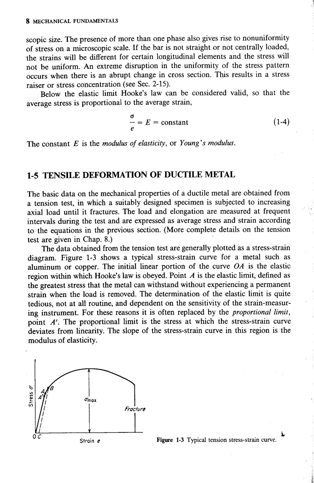
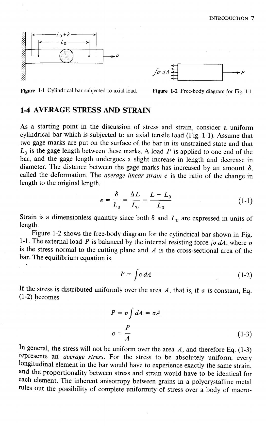
8 MECHANICAL FUNDAMENTALS scopic size.The presence of more than one phase also gives rise to nonuniformity of stress on a microscopic scale.If the bar is not straight or not centrally loaded, the strains will be different for certain longitudinal elements and the stress will not be uniform.An extreme disruption in the uniformity of the stress pattern occurs when there is an abrupt change in cross section.This results in a stress raiser or stress concentration (see Sec.2-15). Below the elastic limit Hooke's law can be considered valid,so that the average stress is proportional to the average strain, -=E constant (1-4) The constant E is the modulus of elasticity,or Young's modulus. 1-5 TENSILE DEFORMATION OF DUCTILE METAL The basic data on the mechanical properties of a ductile metal are obtained from a tension test,in which a suitably designed specimen is subjected to increasing axial load until it fractures.The load and elongation are measured at frequent intervals during the test and are expressed as average stress and strain according to the equations in the previous section.(More complete details on the tension test are given in Chap.8.) The data obtained from the tension test are generally plotted as a stress-strain diagram.Figure 1-3 shows a typical stress-strain curve for a metal such as aluminum or copper.The initial linear portion of the curve O4 is the elastic region within which Hooke's law is obeyed.Point 4 is the elastic limit,defined as the greatest stress that the metal can withstand without experiencing a permanent strain when the load is removed.The determination of the elastic limit is quite tedious,not at all routine,and dependent on the sensitivity of the strain-measur- ing instrument.For these reasons it is often replaced by the proportional limit, point A'.The proportional limit is the stress at which the stress-strain curve deviates from linearity.The slope of the stress-strain curve in this region is the modulus of elasticity. B 可mo' Fracture Stroin e Figure 1-3 Typical tension stress-strain curve