Chapter 24 Physical Pendulum 24.I Introduction.. 24.1.1 Simple Pendulum:Torque Approach..... 24.2 Physical Pendulum. 24.3 Worked Examples4 Example 24.1 Oscillating Rod..4 Example 24.3 Torsional Oscillator Example 24.4 Compound Physical Pendulum.9 Appendix 24A Higher-Order Corrections to the Period for Larger Amplitudes of a Simple Pendulum. 12
Chapter 24 Physical Pendulum 24.1 Introduction........................................................................................................... 1 24.1.1 Simple Pendulum: Torque Approach .......................................................... 1 24.2 Physical Pendulum................................................................................................ 2 24.3 Worked Examples................................................................................................. 4 Example 24.1 Oscillating Rod.................................................................................. 4 Example 24.3 Torsional Oscillator .......................................................................... 7 Example 24.4 Compound Physical Pendulum........................................................ 9 Appendix 24A Higher-Order Corrections to the Period for Larger Amplitudes of a Simple Pendulum ..................................................................................................... 12
Chapter 24 Physical Pendulum ...I had along with me....the Descriptions,with some Drawings of the principal Parts of the Pendulum-Clock which I had made,and as also of them of my then intended Timekeeper for the Longitude at Sea. John Harrison 24.1 Introduction We have already used Newton's Second Law or Conservation of Energy to analyze systems like the spring-object system that oscillate.We shall now use torque and the rotational equation of motion to study oscillating systems like pendulums and torsional springs 24.1.1 Simple Pendulum:Torque Approach Recall the simple pendulum from Chapter 23.3.1.The coordinate system and force diagram for the simple pendulum is shown in Figure 24.1. PR (t 0t)、 mg (a) (b) Figure 24.1 (a)Coordinate system and (b)torque diagram for simple pendulum The torque about the pivot point P is given by 元p=ipm×mg=1f×mg(cos8f-sine)=-Imgsin0k (24.1.1) The z-component of the torque about point P (p).=-mglsin0. (24.1.2) J.Harrison,A Description Concerning Such Mechanisms as will Afford a Nice,or True Mensuration of Time;...(London,1775),p.19. 24-1
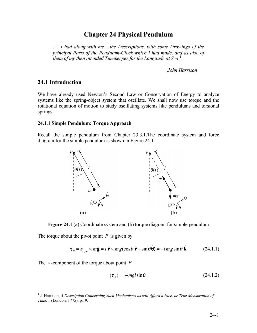
24-1 Chapter 24 Physical Pendulum …. I had along with me….the Descriptions, with some Drawings of the principal Parts of the Pendulum-Clock which I had made, and as also of them of my then intended Timekeeper for the Longitude at Sea. 1 John Harrison 24.1 Introduction We have already used Newton’s Second Law or Conservation of Energy to analyze systems like the spring-object system that oscillate. We shall now use torque and the rotational equation of motion to study oscillating systems like pendulums and torsional springs. 24.1.1 Simple Pendulum: Torque Approach Recall the simple pendulum from Chapter 23.3.1.The coordinate system and force diagram for the simple pendulum is shown in Figure 24.1. (a) (b) Figure 24.1 (a) Coordinate system and (b) torque diagram for simple pendulum The torque about the pivot point P is given by τ P = rP, m × m g = l rˆ × mg(cosθ rˆ − sinθ ˆ θ) = −l mg sinθ kˆ (24.1.1) The z -component of the torque about point P (τ P )z = −mglsinθ . (24.1.2) 1 J. Harrison, A Description Concerning Such Mechanisms as will Afford a Nice, or True Mensuration of Time;…(London, 1775), p.19
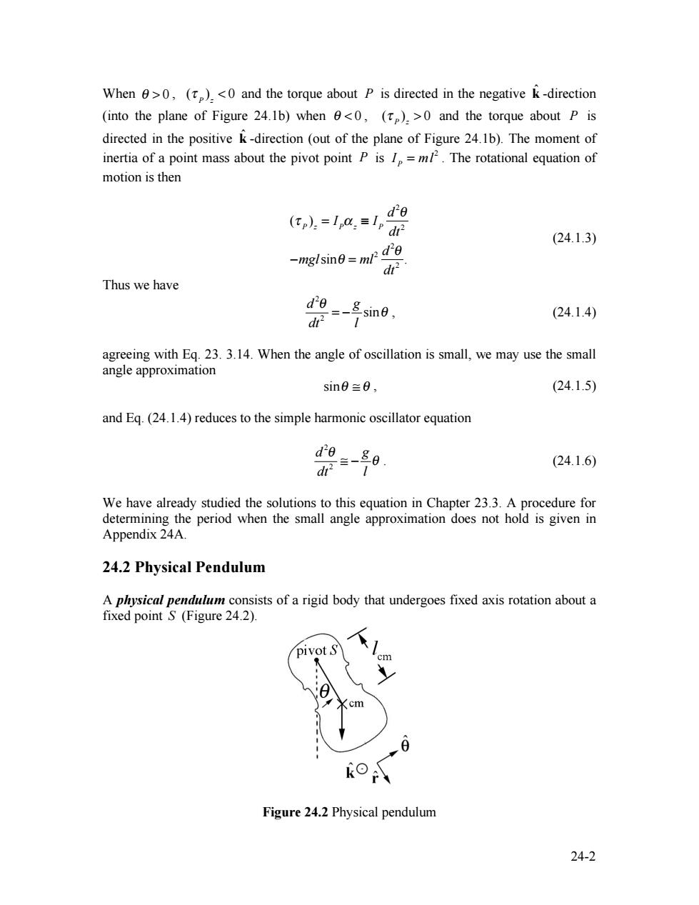
When >0,(and the torque about P is directed in the negative k-direction (into the plane of Figure 24.1b)when <0,()>0 and the torque about P is directed in the positive k-direction(out of the plane of Figure 24.1b).The moment of inertia of a point mass about the pivot point P is I=m12.The rotational equation of motion is then ,l.=1a,=l, do (24.1.3) -mglsine ml2 de dr Thus we have do=_Esine, (24.1.4) agreeing with Eq.23.3.14.When the angle of oscillation is small,we may use the small angle approximation sin0三0, (24.1.5) and Eq.(24.1.4)reduces to the simple harmonic oscillator equation d' dt2 -86 1 (24.1.6) We have already studied the solutions to this equation in Chapter 23.3.A procedure for determining the period when the small angle approximation does not hold is given in Appendix 24A. 24.2 Physical Pendulum A physical pendulum consists of a rigid body that undergoes fixed axis rotation about a fixed point S (Figure 24.2). pivot S cm <cm Figure 24.2 Physical pendulum 24-2
24-2 When θ > 0 , (τ P )z < 0 and the torque about P is directed in the negative kˆ -direction (into the plane of Figure 24.1b) when θ < 0 , (τ P )z > 0 and the torque about P is directed in the positive kˆ -direction (out of the plane of Figure 24.1b). The moment of inertia of a point mass about the pivot point P is IP = ml 2 . The rotational equation of motion is then (τ P )z = IPα z ≡ IP d2 θ dt 2 −mglsinθ = ml 2 d2 θ dt 2 . (24.1.3) Thus we have 2 2 sin d g dt l θ = − θ , (24.1.4) agreeing with Eq. 23. 3.14. When the angle of oscillation is small, we may use the small angle approximation sinθ ≅ θ , (24.1.5) and Eq. (24.1.4) reduces to the simple harmonic oscillator equation 2 2 d g dt l θ ≅ − θ . (24.1.6) We have already studied the solutions to this equation in Chapter 23.3. A procedure for determining the period when the small angle approximation does not hold is given in Appendix 24A. 24.2 Physical Pendulum A physical pendulum consists of a rigid body that undergoes fixed axis rotation about a fixed point S (Figure 24.2). Figure 24.2 Physical pendulum
The gravitational force acts at the center of mass of the physical pendulum.Denote the distance of the center of mass to the pivot point S by lem.The torque analysis is nearly identical to the simple pendulum.The torque about the pivot point S is given by 元、=s.m×mg=li×mg(cos0f-sin8)=-lmgsin0k (24.2.1) Following the same steps that led from Equation (24.1.1)to Equation (24.1.4),the rotational equation for the physical pendulum is -mgln sine-Is df d20 (24.2.2) where Is the moment of inertia about the pivot point S.As with the simple pendulum, for small angles sin=,Equation (24.2.2)reduces to the simple harmonic oscillator equation d'e mglem (24.2.3) Is The equation for the angle e(t)is given by 0(t)=Acos(@1)+Bsin(@1), (24.2.4) where the angular frequency is given by 0兰 mg lem (physical pendulum), (24.2.5) and the period is T= 2π (physical pendulum). (24.2.6) 00 mg lem Substitute the parallel axis theorem,I=minto Eq.(24.2.6)with the result that T=2π (physical pendulum). (24.2.7) Thus,if the object is "small"in the sense thatm the expressions for the physical pendulum reduce to those for the simple pendulum.The z-component of the angular velocity is given by 24-3
24-3 The gravitational force acts at the center of mass of the physical pendulum. Denote the distance of the center of mass to the pivot point S by cml . The torque analysis is nearly identical to the simple pendulum. The torque about the pivot point S is given by τ S = rS , cm × m g = l cmrˆ × mg(cosθ rˆ − sinθ ˆ θ) = −l cmmg sinθ kˆ . (24.2.1) Following the same steps that led from Equation (24.1.1) to Equation (24.1.4), the rotational equation for the physical pendulum is − mglcm sinθ = IS d2 θ dt 2 , (24.2.2) where IS the moment of inertia about the pivot point S . As with the simple pendulum, for small angles sinθ ≈θ , Equation (24.2.2) reduces to the simple harmonic oscillator equation d2 θ dt 2 − mglcm IS θ . (24.2.3) The equation for the angle θ(t) is given by θ(t) = Acos(ω0 t)+ Bsin(ω0 t), (24.2.4) where the angular frequency is given by ω0 mg l cm IS (physical pendulum) , (24.2.5) and the period is T = 2π ω0 2π IS mg l cm (physical pendulum). (24.2.6) Substitute the parallel axis theorem, IS = ml cm 2 + Icm , into Eq. (24.2.6) with the result that T 2π l cm g + Icm mg l cm (physical pendulum). (24.2.7) Thus, if the object is “small” in the sense that Icm << ml cm 2 , the expressions for the physical pendulum reduce to those for the simple pendulum. The z-component of the angular velocity is given by
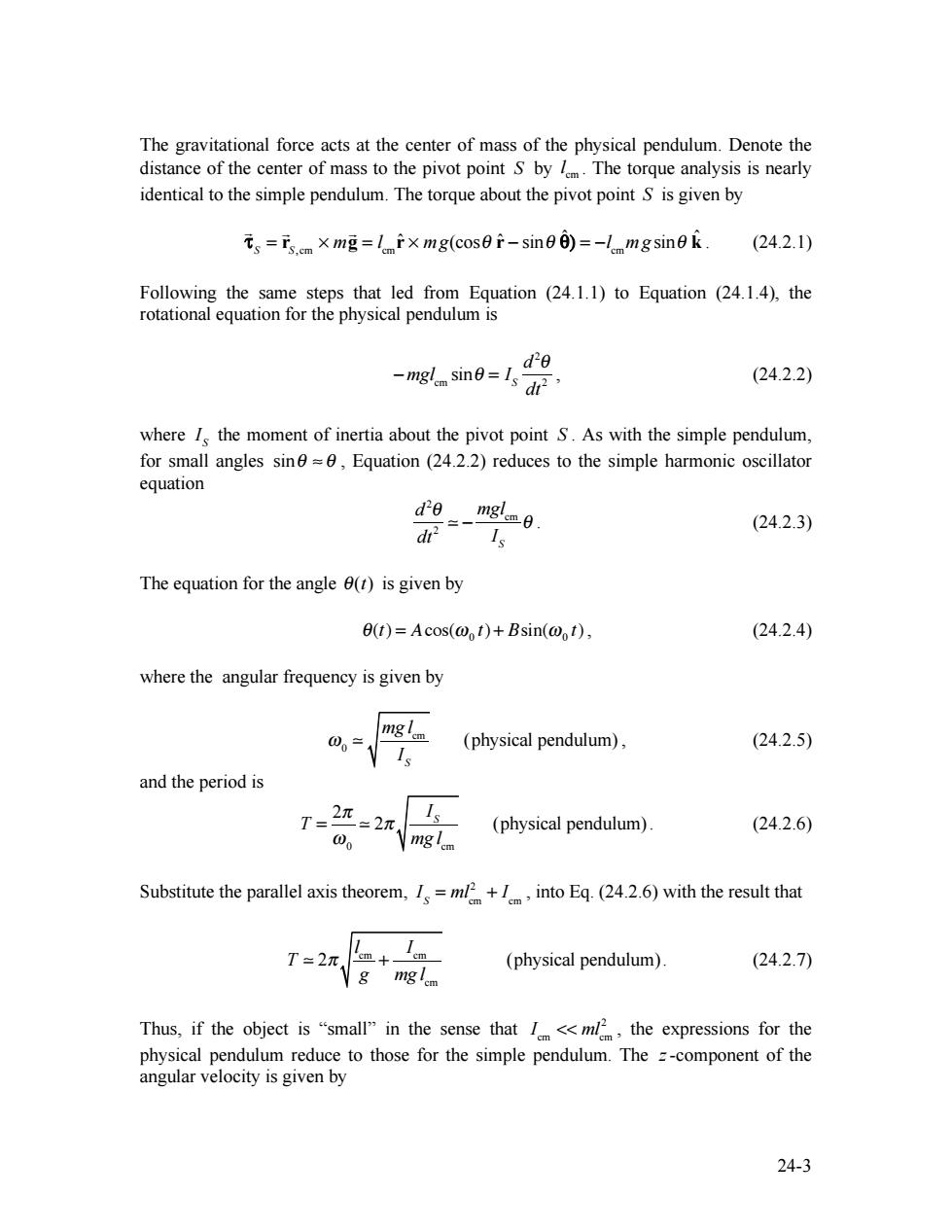
a.(0=B0=-0,4sina,)+,Bcox@,). (24.2.8) dt The coefficients 4 and B can be determined form the initial conditions by setting t=0 in Egs.(24.2.4)and(24.2.8)resulting in the conditions that A=(1=0)≡0 B=0:1=0=02 (24.2.9) 一三一 00 00 Therefore the nfortheane(r)d))reve by O)=0,cos!)+sin,). (24.2.10) 0.0= ed)=-0,8sin(@,0+0ncos(0,) (24.2.11) 24.3 Worked Examples Example 24.1 Oscillating Rod A physical pendulum consists of a uniform rod of length d and mass m pivoted at one end.The pendulum is initially displaced to one side by a small angle e and released from rest with <<1.Find the period of the pendulum.Determine the period of the pendulum using (a)the torque method and(b)the energy method. pivot P ⊙k *8 Figure 24.3 Oscillating rod (a)Torque Method:with our choice of rotational coordinate system the angular acceleration is given by 24-4
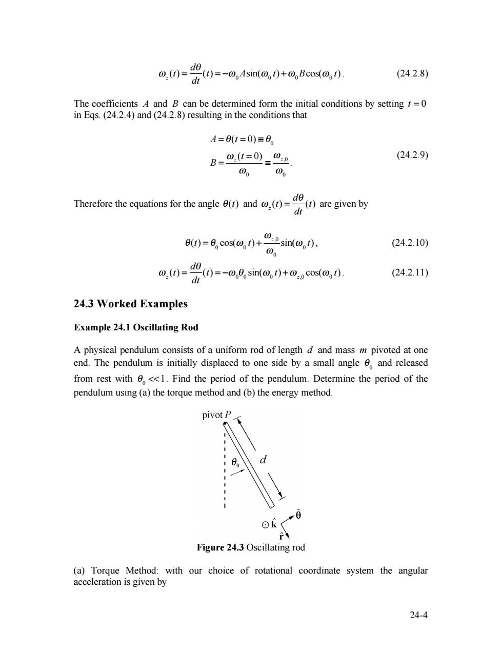
24-4 ω z (t) = dθ dt (t) = −ω0Asin(ω0 t) +ω0Bcos(ω0 t). (24.2.8) The coefficients A and B can be determined form the initial conditions by setting t = 0 in Eqs. (24.2.4) and (24.2.8) resulting in the conditions that A = θ(t = 0) ≡ θ0 B = ω z (t = 0) ω0 ≡ ω z,0 ω0 . (24.2.9) Therefore the equations for the angle θ(t) and ω z (t) = dθ dt (t) are given by θ(t) = θ0 cos(ω0 t) + ω z,0 ω0 sin(ω0 t), (24.2.10) ω z (t) = dθ dt (t) = −ω0 θ0 sin(ω0 t) +ω z,0 cos(ω0 t). (24.2.11) 24.3 Worked Examples Example 24.1 Oscillating Rod A physical pendulum consists of a uniform rod of length d and mass m pivoted at one end. The pendulum is initially displaced to one side by a small angle θ0 and released from rest with θ0 <<1. Find the period of the pendulum. Determine the period of the pendulum using (a) the torque method and (b) the energy method. Figure 24.3 Oscillating rod (a) Torque Method: with our choice of rotational coordinate system the angular acceleration is given by