
Chapter 5 Planar Kinematic Modeling and Analysis Modeling and analysis techniques 1. Draw a clear diagram of the system to be modeled 2. Select and number bodies and kinematic joints between pairs of bodies 3. Count the number of the constraint equations nh 4. Calculate DOF=3nb-nh 5. If DOF <=0,eliminate the redundant constraints 6. Define DOF drivers to specify the motion of the system 7. Make drawings of each body in the system,defining the body-fixed x'-y'frames and data required for each of the kinematic joints and drivers selected 8. Use a reasonable sketch or diagram of the system to estimate the position and orientation variables to initiate the assembly process of analysis
Chapter 5 Planar Kinematic Modeling and Analysis 1. Draw a clear diagram of the system to be modeled 2. Select and number bodies and kinematic joints between pairs of bodies 3. Count the number of the constraint equations nh 4. Calculate DOF=3nb-nh 5. If DOF < = 0, eliminate the redundant constraints 6. Define DOF drivers to specify the motion of the system 7. Make drawings of each body in the system, defining the body-fixed x’-y’ frames and data required for each of the kinematic joints and drivers selected 8. Use a reasonable sketch or diagram of the system to estimate the position and orientation variables to initiate the assembly process of analysis Modeling and analysis techniques
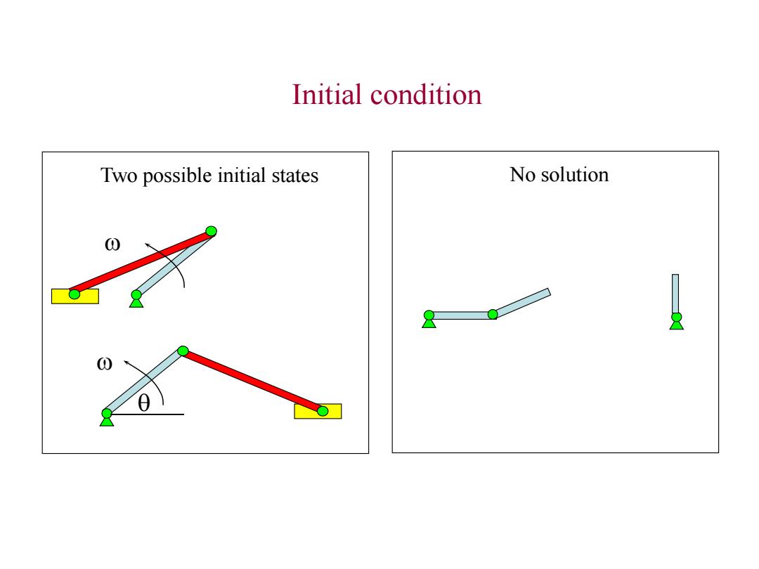
Initial condition Two possible initial states No solution 0
Initial condition Two possible initial states w w No solution q

Initial condition assembly of the system The user may employ graphical estimates of the position and orientation of each body to create g o,how to obtain the initial assembled configuration g a The objective is to minimize 平(q,to,r)=q-q°)y(q-q)+rΦ'(q,to)(q,t) to get q(r) r>0 is a weighting constant that places relative emphasis on deviation from the qo ga lim g(r)
Initial condition assembly of the system The user may employ graphical estimates of the position and orientation of each body to create q 0 , how to obtain the initial assembled configuration q a ? The objective is to minimize ( , , ) ( , ) ( , ) 0 0 0 0 0 t r r t t T T q q q q q q q r > 0 is a weighting constant that places relative emphasis on deviation from the q0 lim (r) r a q q to get q(r)
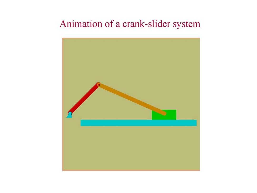
Animation of a crank-slider system
Animation of a crank-slider system
Kinematic analysis of a crank-slider system B2 Driving equation B3 1= +ot 4 l.If o is increased from2πto4π,the ratios of maximum velocity and acceleration are approximately 2 and 4. 2.For o=2n,if l is decreased from 3.5,to 2.5,to 2.2,to 2.1,position and velocity are moderately sensitive to variation in 1,acceleration,on the other hand,shows extreme sensitivity,especially near its extreme left and right position. 3.Peak variation between /=2.2 and /2.1 is much greater than /=3.5 and 1 2.5 4. If is further decreased to 1.9,for t approaches 0.074s,both the velocity and acceleration of the slider approach infinity
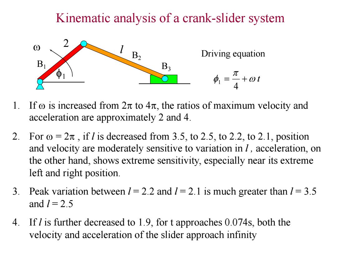
Kinematic analysis of a crank-slider system w f1 Driving equation w t f 4 1 1. If w is increased from 2 to 4, the ratios of maximum velocity and acceleration are approximately 2 and 4. 2. For w = 2 , if l is decreased from 3.5, to 2.5, to 2.2, to 2.1, position and velocity are moderately sensitive to variation in l , acceleration, on the other hand, shows extreme sensitivity, especially near its extreme left and right position. 3. Peak variation between l = 2.2 and l = 2.1 is much greater than l = 3.5 and l = 2.5 4. If l is further decreased to 1.9, for t approaches 0.074s, both the velocity and acceleration of the slider approach infinity 2 l B1 B2 B3