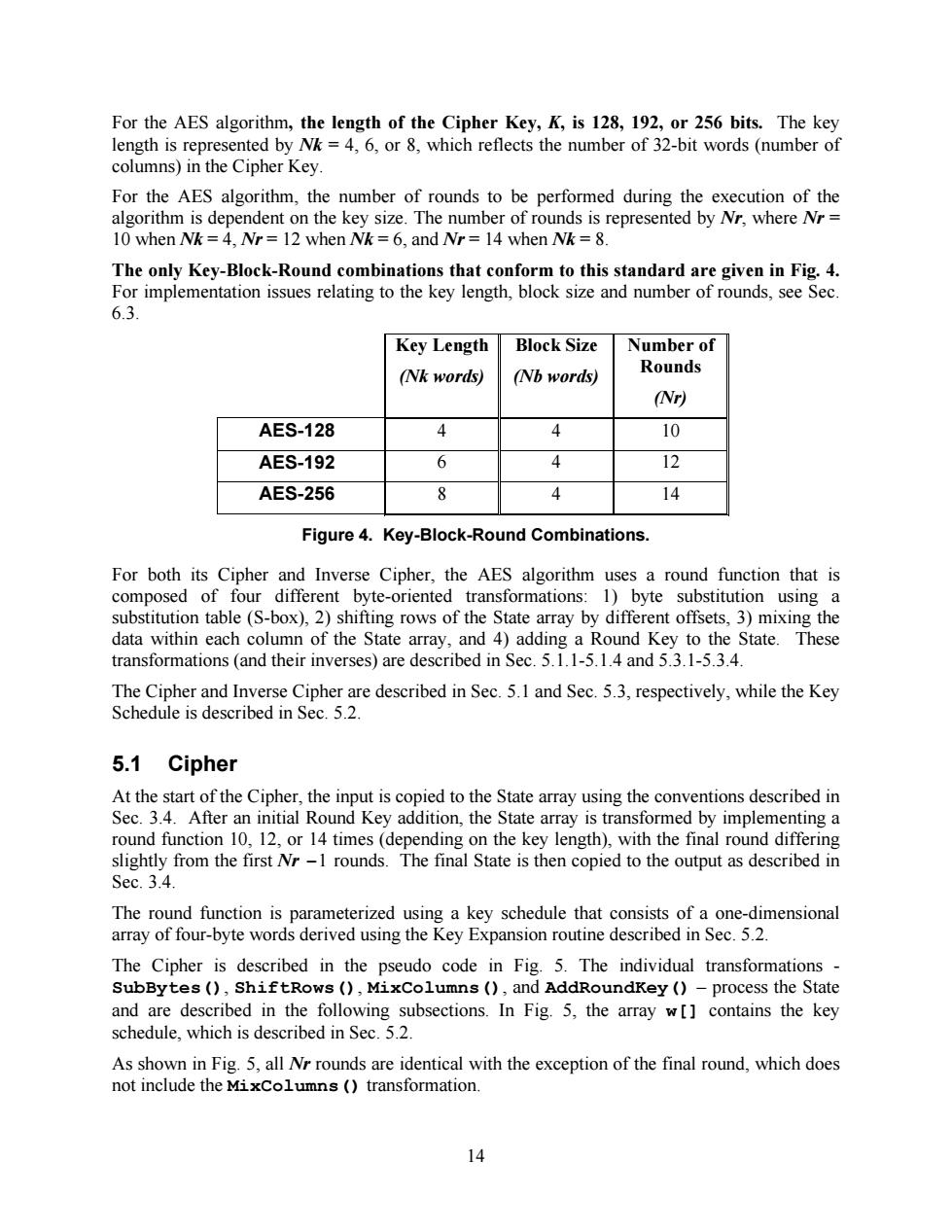
For the AES algorithm,the length of the Cipher Key,K,is 128,192,or 256 bits.The key length is represented by Nk=4,6,or 8,which reflects the number of 32-bit words(number of columns)in the Cipher Key. For the AES algorithm,the number of rounds to be performed during the execution of the algorithm is dependent on the key size.The number of rounds is represented by Nr,where Nr= 10 when Nk=4,Nr=12 when Nk=6,and Nr=14 when Nk =8. The only Key-Block-Round combinations that conform to this standard are given in Fig.4. For implementation issues relating to the key length,block size and number of rounds,see Sec. 6.3. Key Length Block Size Number of (Nk words) (Nb words) Rounds (Nr) AES-128 4 4 10 AES-192 6 4 12 AES-256 8 4 14 Figure 4.Key-Block-Round Combinations. For both its Cipher and Inverse Cipher,the AES algorithm uses a round function that is composed of four different byte-oriented transformations:1)byte substitution using a substitution table(S-box),2)shifting rows of the State array by different offsets,3)mixing the data within each column of the State array,and 4)adding a Round Key to the State.These transformations (and their inverses)are described in Sec.5.1.1-5.1.4 and 5.3.1-5.3.4 The Cipher and Inverse Cipher are described in Sec.5.1 and Sec.5.3,respectively,while the Key Schedule is described in Sec.5.2. 5.1 Cipher At the start of the Cipher,the input is copied to the State array using the conventions described in Sec.3.4.After an initial Round Key addition,the State array is transformed by implementing a round function 10,12,or 14 times (depending on the key length),with the final round differing slightly from the first Nr-1 rounds.The final State is then copied to the output as described in Sec.3.4. The round function is parameterized using a key schedule that consists of a one-dimensional array of four-byte words derived using the Key Expansion routine described in Sec.5.2 The Cipher is described in the pseudo code in Fig.5.The individual transformations SubBytes(),ShiftRows(),MixColumns(),and AddRoundKey ()-process the State and are described in the following subsections.In Fig.5,the array w[]contains the key schedule,which is described in Sec.5.2. As shown in Fig.5,all Nr rounds are identical with the exception of the final round,which does not include the MixColumns (transformation. 14
14 For the AES algorithm, the length of the Cipher Key, K, is 128, 192, or 256 bits. The key length is represented by Nk = 4, 6, or 8, which reflects the number of 32-bit words (number of columns) in the Cipher Key. For the AES algorithm, the number of rounds to be performed during the execution of the algorithm is dependent on the key size. The number of rounds is represented by Nr, where Nr = 10 when Nk = 4, Nr = 12 when Nk = 6, and Nr = 14 when Nk = 8. The only Key-Block-Round combinations that conform to this standard are given in Fig. 4. For implementation issues relating to the key length, block size and number of rounds, see Sec. 6.3. Key Length (Nk words) Block Size (Nb words) Number of Rounds (Nr) AES-128 4 4 10 AES-192 6 4 12 AES-256 8 4 14 Figure 4. Key-Block-Round Combinations. For both its Cipher and Inverse Cipher, the AES algorithm uses a round function that is composed of four different byte-oriented transformations: 1) byte substitution using a substitution table (S-box), 2) shifting rows of the State array by different offsets, 3) mixing the data within each column of the State array, and 4) adding a Round Key to the State. These transformations (and their inverses) are described in Sec. 5.1.1-5.1.4 and 5.3.1-5.3.4. The Cipher and Inverse Cipher are described in Sec. 5.1 and Sec. 5.3, respectively, while the Key Schedule is described in Sec. 5.2. 5.1 Cipher At the start of the Cipher, the input is copied to the State array using the conventions described in Sec. 3.4. After an initial Round Key addition, the State array is transformed by implementing a round function 10, 12, or 14 times (depending on the key length), with the final round differing slightly from the first Nr -1 rounds. The final State is then copied to the output as described in Sec. 3.4. The round function is parameterized using a key schedule that consists of a one-dimensional array of four-byte words derived using the Key Expansion routine described in Sec. 5.2. The Cipher is described in the pseudo code in Fig. 5. The individual transformations - SubBytes(), ShiftRows(), MixColumns(), and AddRoundKey() – process the State and are described in the following subsections. In Fig. 5, the array w[] contains the key schedule, which is described in Sec. 5.2. As shown in Fig. 5, all Nr rounds are identical with the exception of the final round, which does not include the MixColumns() transformation
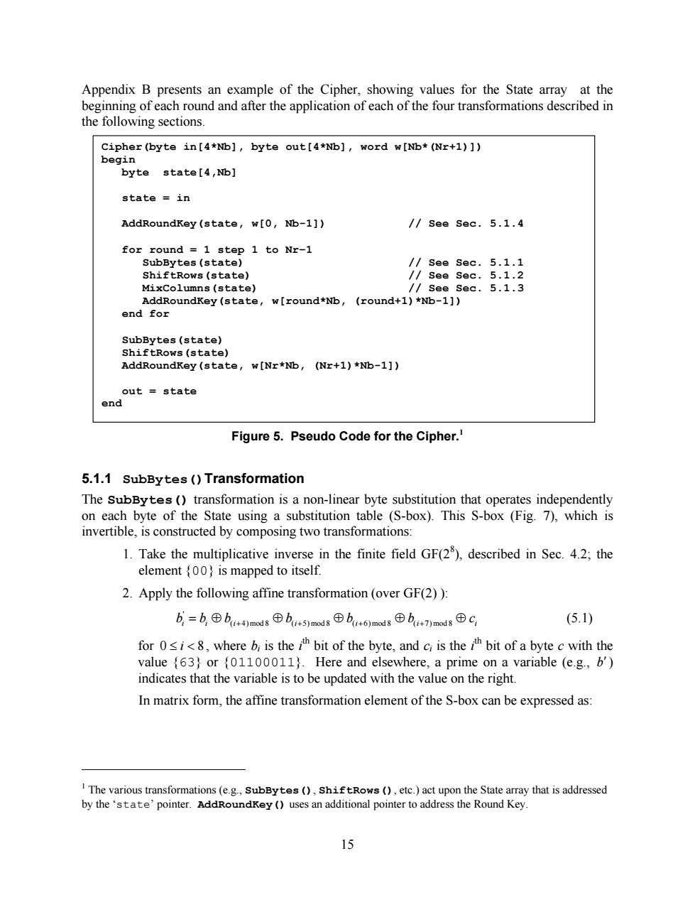
Appendix B presents an example of the Cipher,showing values for the State array at the beginning of each round and after the application of each of the four transformations described in the following sections. Cipher (byte in[4*Nb],byte out[4*Nb],word w[Nb*(Nr+1)]) begin byte:state[4,Nb】 state in AddRoundKey (state,w[0,Nb-1]) /See Sec.5.1.4 for round 1 step 1 to Nr-1 SubBytes (state) /See Sec.5.1.1 ShiftRows(state) /See Sec.5.1.2 MixColumns (state) /see sec.5.1.3 AddRoundKey(state,w[round*Nb, (round+1)*Nb-1]) end for SubBytes(state) ShiftRows (state) AddRoundKey(state,w[Nr*Nb,(Nr+1)*Nb-1]) out state end Figure 5.Pseudo Code for the Cipher. 5.1.1 SubBytes ()Transformation The SubBytes (transformation is a non-linear byte substitution that operates independently on each byte of the State using a substitution table (S-box).This S-box (Fig.7),which is invertible,is constructed by composing two transformations: 1.Take the multiplicative inverse in the finite field GF(2),described in Sec.4.2;the element (00)is mapped to itself. 2.Apply the following affine transformation (over GF(2)): b,=b,⊕bi+4)md8⊕b+5)modsb+6)madg⊕b+7)mod8⊕C (5.1) for 0i,where b is theh bit of the byte,and cr is the h bit of a byte c with the value {63)or {01100011).Here and elsewhere,a prime on a variable (e.g.,b') indicates that the variable is to be updated with the value on the right. In matrix form,the affine transformation element of the S-box can be expressed as: I The various transformations(e.g.,SubBytes(),shiftRows(),etc.)act upon the State array that is addressed by the 'state'pointer.AddRoundKey (uses an additional pointer to address the Round Key. 15
15 Appendix B presents an example of the Cipher, showing values for the State array at the beginning of each round and after the application of each of the four transformations described in the following sections. Figure 5. Pseudo Code for the Cipher.1 5.1.1 SubBytes()Transformation The SubBytes() transformation is a non-linear byte substitution that operates independently on each byte of the State using a substitution table (S-box). This S-box (Fig. 7), which is invertible, is constructed by composing two transformations: 1. Take the multiplicative inverse in the finite field GF(28 ), described in Sec. 4.2; the element {00} is mapped to itself. 2. Apply the following affine transformation (over GF(2) ): i i i i i i i b = b Å b Å b Å b Å b Å c ( +4) mod 8 ( +5) mod 8 ( +6) mod 8 ( +7) mod 8 ' (5.1) for 0 £ i < 8 , where bi is the i th bit of the byte, and ci is the i th bit of a byte c with the value {63} or {01100011}. Here and elsewhere, a prime on a variable (e.g., b¢) indicates that the variable is to be updated with the value on the right. In matrix form, the affine transformation element of the S-box can be expressed as: 1 The various transformations (e.g., SubBytes(), ShiftRows(), etc.) act upon the State array that is addressed by the ‘state’ pointer. AddRoundKey() uses an additional pointer to address the Round Key. Cipher(byte in[4*Nb], byte out[4*Nb], word w[Nb*(Nr+1)]) begin byte state[4,Nb] state = in AddRoundKey(state, w[0, Nb-1]) // See Sec. 5.1.4 for round = 1 step 1 to Nr–1 SubBytes(state) // See Sec. 5.1.1 ShiftRows(state) // See Sec. 5.1.2 MixColumns(state) // See Sec. 5.1.3 AddRoundKey(state, w[round*Nb, (round+1)*Nb-1]) end for SubBytes(state) ShiftRows(state) AddRoundKey(state, w[Nr*Nb, (Nr+1)*Nb-1]) out = state end