
.The data rate is R=log,M/T bits/s. Then 2b=R/W=p,which is the spectral efficiency of a modulation scheme(bits s/Hz).or p=是1g,M bits/2D The average energy of A per dimension is given by E=E/N If the Msignal points inA are assumed to be equiprobable,then f 2,fm2 To simplify performance assessment,we define a figure of merit (CFM)for a constellation as 5e山 (2.5) As we have stated in Chapter 1,from the signal space viewpoint,the data modulation can be viewed as a two-step process:a signal mapper followed by a simple waveform converter.A signal mapper performs the mapping of a binary vector of length logM into one of a const thethe siaon Mapping is not airary.clever shoices Iead to betcr lation ally,the binar vector performance over noisy channels. In some channels it is suitable to label points that are close in Euclidean distance to map to being close in Hamming distance.An example for such mapping is the Gray-mapping Fig 2.6 illustrates an example. 1
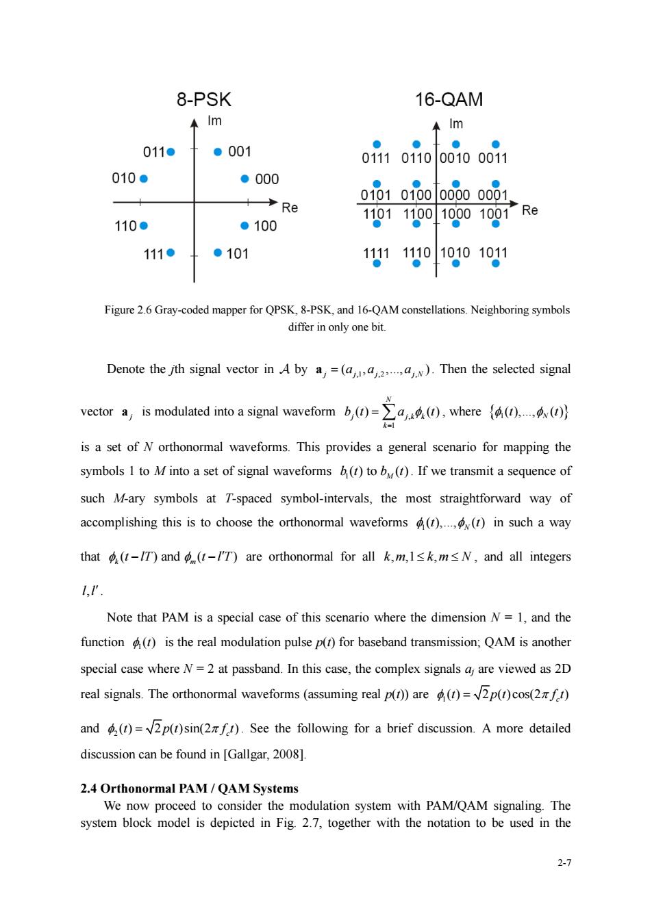
2-6 ⚫ The data rate is 2 R M T = log / bits/s. ⚫ Then 2 / b R W = , which is the spectral efficiency of a modulation scheme (bits / s / Hz), or 2 2 log M N = bits / 2D ⚫ The average energy of per dimension is given by Ed = EN / N If the M signal points in are assumed to be equiprobable, then 2 1 1 || || M N j j E M = = a and 2 1 1 || || M d j j E MN = = a ⚫ To simplify performance assessment, we define a figure of merit (CFM) for a constellation as 2 min ( ) 4 d d E (2.5) As we have stated in Chapter 1, from the signal space viewpoint, the data modulation can be viewed as a two-step process: a signal mapper followed by a simple waveform converter. A signal mapper performs the mapping of a binary vector of length log2M into one of the signal points in a constellation of size M. Usually, the binary vector is referred to as the label of the signal point. Mapping is not arbitrary, clever choices lead to better performance over noisy channels. In some channels it is suitable to label points that are close in Euclidean distance to map to being close in Hamming distance. An example for such mapping is the Gray-mapping. Fig. 2.6 illustrates an example
8-PSK 16-QAM ↑m ←lm 011● ●001 01i101i00010o0i1 010● ●000 Re 0101010000000001. 110● ●100 1101110010o01o07Re 111● ●101 111110101010g1 Figure 26 Gray-coded mapper for QPSK.8-PSK.and 16-QAM constellations.Neighboring symbols differ in only one bit. Denote the jth signal vector in A by a,=(a).Then the selected signal is a set of N orthonormal waveforms.This provides a general scenario for mapping the symbols I to M into a set of signal waveforms b(r)to b().If we transmit a sequence of such M-ary symbols at T-spaced symbol-intervals,the most straightforward way of accomplishing this is to choose the orthonormal waveforms).(t)in such a way that-T)and (-/'T)are orthonormal for all k,m,Isk,m<N,and all integers Note that PAM is a special case of this scenario where the dimension N=1,and the function)is the real modulation pulse p(r)for baseband transmission:QAM is another special case where N=2 at passband.In this case,the complex signals a are viewed as 2D real signals.The orthonormal waveforms (assuming real p())are)=2p()cos(2) and()=2p(r)sin(f).See the following for a brief discussion.A more detailed discussion can be found in [Gallgar,200] 2.4 Orthonormal PAM/QAM Systems We now proceed to consider the modulation system with PAM/QAM signaling.The system block model is depicted in Fig.2.7.together with the notation to be used in the 2
2-7 Figure 2.6 Gray-coded mapper for QPSK, 8-PSK, and 16-QAM constellations. Neighboring symbols differ in only one bit. Denote the jth signal vector in by ,1 ,2 , ( , ,., ) j j j j N a = a a a . Then the selected signal vector j a is modulated into a signal waveform , 1 ( ) ( ) N j j k k k b t a t = = , where 1 ( ),., ( ) t t N is a set of N orthonormal waveforms. This provides a general scenario for mapping the symbols 1 to M into a set of signal waveforms 1 ( ) to ( ) M b t b t . If we transmit a sequence of such M-ary symbols at T-spaced symbol-intervals, the most straightforward way of accomplishing this is to choose the orthonormal waveforms 1 ( ),., ( ) N t t in such a way that ( ) and ( ) k m t lT t l T − − are orthonormal for all k m k m N , ,1 , , and all integers ll, . Note that PAM is a special case of this scenario where the dimension N = 1, and the function 1 ()t is the real modulation pulse p(t) for baseband transmission; QAM is another special case where N = 2 at passband. In this case, the complex signals aj are viewed as 2D real signals. The orthonormal waveforms (assuming real p(t)) are 1 ( ) 2 ( )cos(2 ) c t p t f t = and 2 ( ) 2 ( )sin(2 ) c t p t f t = . See the following for a brief discussion. A more detailed discussion can be found in [Gallgar, 2008]. 2.4 Orthonormal PAM / QAM Systems We now proceed to consider the modulation system with PAM/QAM signaling. The system block model is depicted in Fig. 2.7, together with the notation to be used in the
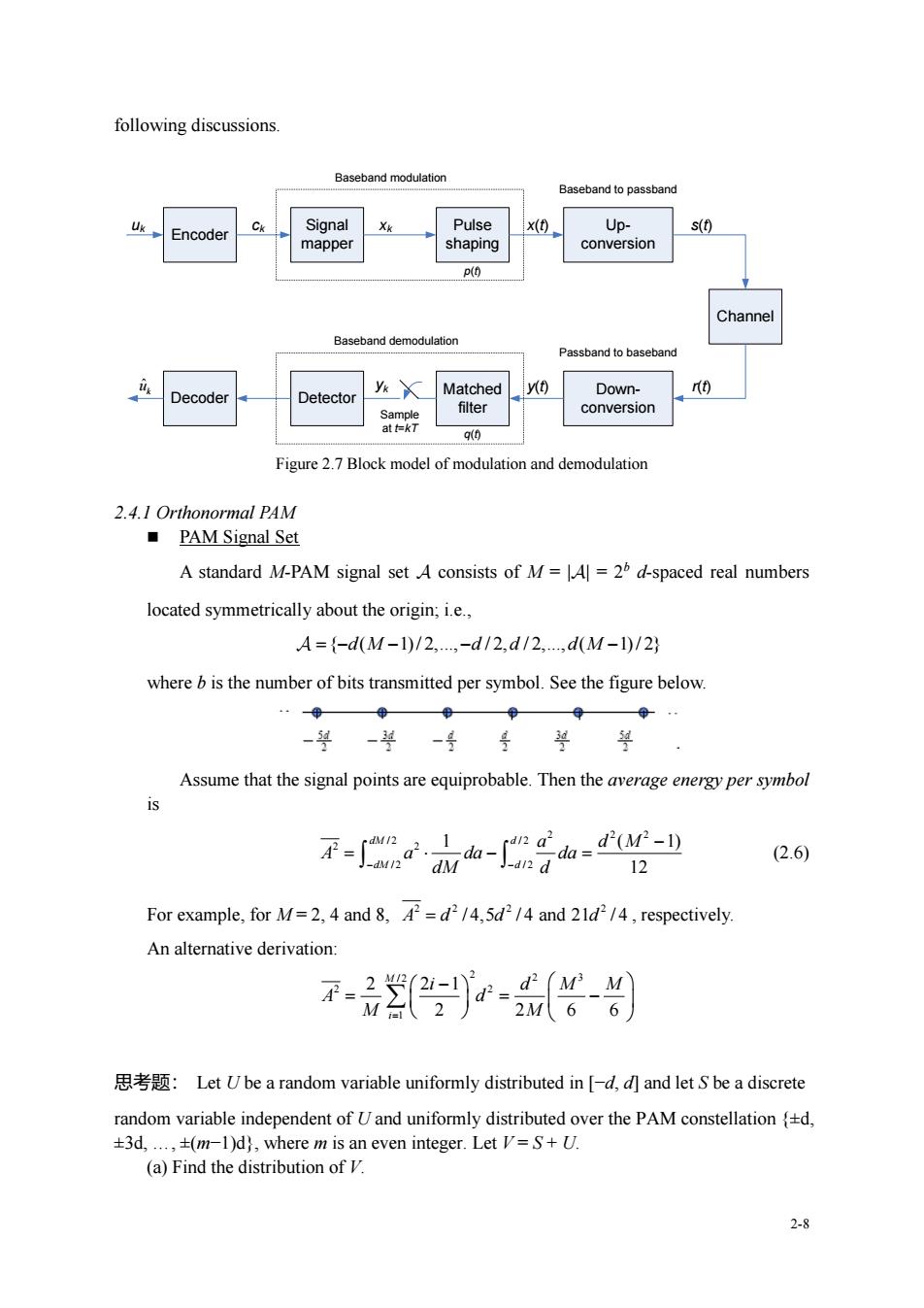
following discussions. Baseband modulation Baseband topassband -Encoder Signal Pulse x(t) Up- s(t) mapper shaping conversion P(O and democ ulation Passband to baseban Decoder etector y Matched yt) Down- conversion 90 Figure 2.7 Block model of modulation and demodulation 2.4.1 Orthonormal PAM ■PAM Signal Set A standard M-PAM signal set A consists of M=A]=2d-spaced real numbers located symmetrically about the origin;i.e., A={-d(M-1)/2,-d/2,d/2,d(M-l0/2} where bis the number of bits transmitted per symbol.See the figure below Assume that the signal points are equiprobable.Then the average energy per symbol 不-小心-音山g- (2.6) 12 For example,for M.4 and/4.5d/4 and /,respectively. An alternative derivation 思考题:Let Ube a random variable uniformly distributed in-d,and letbe adiscrete random variable independent of Uand uniformly distributed over the PAM constellationd, +3d,.,(m-1)d),where m is an even integer.Let V=+U. (a)Find the distribution of 2-8
2-8 following discussions. Encoder Signal mapper Pulse shaping Up- conversion uk ck xk x(t) Baseband modulation Baseband to passband s(t) Channel Down- conversion Passband to baseband Matched filter Decoder Detector y(t) r(t) Sample at t=kT yk Baseband demodulation p(t) q(t) ˆ k u Figure 2.7 Block model of modulation and demodulation 2.4.1 Orthonormal PAM ◼ PAM Signal Set A standard M-PAM signal set consists of M = || = 2b d-spaced real numbers located symmetrically about the origin; i.e., = − − − − { ( 1) / 2,., / 2, / 2,., ( 1) / 2} d M d d d M where b is the number of bits transmitted per symbol. See the figure below. Assume that the signal points are equiprobable. Then the average energy per symbol is 2 2 2 / 2 / 2 2 2 / 2 / 2 1 ( 1) 12 dM d dM d a d M A a da da − − dM d − = − = (2.6) For example, for M = 2, 4 and 8, 2 2 2 2 A d d d = / 4,5 / 4 and 21 / 4 , respectively. An alternative derivation: 2 / 2 2 3 2 2 1 2 2 1 2 2 6 6 M i i d M M A d M M = − = = − 思考题: Let U be a random variable uniformly distributed in [−d, d] and let S be a discrete random variable independent of U and uniformly distributed over the PAM constellation {±d, ±3d, ., ±(m−1)d}, where m is an even integer. Let V = S + U. (a) Find the distribution of V
(b)Find the variance of Uand that of V. (e)Use pa (b)todetermine the varianc f(the average energy of thePAMwith uniform distribution.) ■PAM Modulator A PAM modulator converts a discrete-time sequencex kEZ of real symbols into a continuous-time real waveform x0=∑xP1-k灯) where T is the symbol interval,p(r)is the basic modulation pulse,and xA. A PAM system is said to be orthonormal if (p-kT),p-jT)》=d- that is)=ip(t-kT) With the assumption that the underlying channel model is an ideal AWGN channel. the received basebar d waveform is given by )=x0+0 In an orthonormal PAM system,the sequenceof matched-filter outputs is given by y=((I),p1-kT)》=x4+n we obtain without loss of optimality an cquivalent discrete-time GN channel y=x+n 2.4.2 Orthonormal OAM ■QAM Signal Set (MxM)-QAM signal set consists of the Cartesian product of two A=a=(a'+ja")la'EA'.a"EA') whereA'=(-d(M-1)/2.-d/2,d/2.d(M-1)/2).Thus the size of A is Al=M, and the number of bits per symbol is 2log2M=2b.See Fig.2.8 for examples.Assuming that the symbols in A are equiprobable,the average energy per complex symbol is F=2×dM-dM- 2 (2.7) 2.9
2-9 (b) Find the variance of U and that of V . (c) Use part (b) to determine the variance of S. (i.e., the average energy of the PAM with uniform distribution.) ◼ PAM Modulator A PAM modulator converts a discrete-time sequence {xk, k} of real symbols into a continuous-time real waveform ( ) ( ) k k x t x p t kT = − where T is the symbol interval, p(t) is the basic modulation pulse, and xk . A PAM system is said to be orthonormal if ( ), ( ) k j p t kT p t jT − − = − that is {k(t)} = {p(t-kT)}. With the assumption that the underlying channel model is an ideal AWGN channel, the received baseband waveform is given by y(t) = x(t) + n(t) In an orthonormal PAM system, the sequence {yk} of matched-filter outputs is given by ( ), ( ) k k k y y t p t kT x n = − = + Thus, we obtain without loss of optimality an equivalent discrete-time AWGN channel model y = x + n 2.4.2 Orthonormal QAM ◼ QAM Signal Set A standard (MM)-QAM signal set consists of the Cartesian product of two standard M-PAM d-spaced signal set; i.e., = = + a a ja a a ( ' '') | ' , '' ' ' where ' = − − − − { ( 1) / 2,., / 2, / 2,., ( 1) / 2} d M d d d M . Thus the size of is || = M2 , and the number of bits per symbol is 2log2M = 2b. See Fig. 2.8 for examples. Assuming that the symbols in are equiprobable, the average energy per complex symbol is 2 2 2 2 2 ( 1) ( 1) 2 12 6 d M d M A − − = = (2.7)
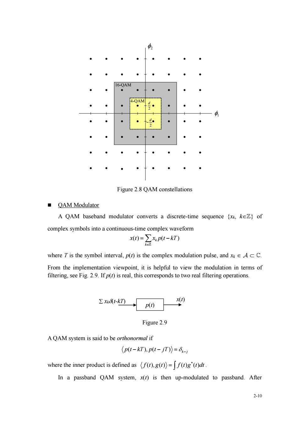
4-QAM Figure 2.8 QAM constellations ■QAM Modulator A QAM baseband modulator converts a discrete-time sequence kZof complex symbols into a continuous-time complex waveform x()=∑P-kT) where T is the symbol interval,p(t)is the complex modulation pulse,and xAcC. From the impementa tion viewpoint,it is helpful to view the modulation in terms of filtering,see Fig.2.9.If p()is real,this corresponds to two real filtering operations. znak009 Figure 2.9 AQAM system is said to be orthonormal if (pu-kT),p1-jT))=6- where the inner product is defined as (().g()=f()g'(d In a passband QAM system,x(r)is then up-modulated to passband.After 2-10
2-10 1 2 16-QAM 4-QAM 2 d 2 d − Figure 2.8 QAM constellations ◼ QAM Modulator A QAM baseband modulator converts a discrete-time sequence {xk, k} of complex symbols into a continuous-time complex waveform ( ) ( ) k k x t x p t kT = − where T is the symbol interval, p(t) is the complex modulation pulse, and xk . From the implementation viewpoint, it is helpful to view the modulation in terms of filtering, see Fig. 2.9. If p(t) is real, this corresponds to two real filtering operations. Figure 2.9 A QAM system is said to be orthonormal if ( ), ( ) k j p t kT p t jT − − = − where the inner product is defined as * f t g t f t g t dt ( ), ( ) ( ) ( ) = . In a passband QAM system, x(t) is then up-modulated to passband. After p(t) x(t) xk(t-kT)