
附件24.2 国he2 d hid ei年a (2)The flow rate in pipe from formula (2-30): 三2元 integrate it we obtain, (231) 1281 (3)Average velocity in pipe According to the definition of average velocity. g 1 R' R d (2-32) Fomula (2-32)says that the average of the maxmm elocity Chapter2 Fundamental Hydranlic Fhid Nechanies (4)Losses along circle parallel pipe From formula (2-32).the loss is: 32 ul p入= (2-33) d/2 Do some change,The formula(2-33)can be written in 64 647m Re d 2 =白四 (2-340 Where is the resistance coefficient along a circle pipe.In theory but in a pactical caseora metal pipe. 80 D
附件 24.2 24
附件24.2 Chapter2 Fundamental Hydranlie Flid Mechanies 2.Losses in parallel pipe at turbulence flow When tubulence flow has happened,The experiment has shown that resistance coefficientis A=I(R.A) The resistace coefficient can be calculated by experimental formula as follows for water-power slippery pipe. 1=0.3164R02 4000<Re<103 A=0.032+0.211R0237 103<Re<3×10⁵ (2-35) =(,+174 (2-36) Hereis related with material of pipe.such as stee tube 04mmcopper pipe 0.0015~0.01mm,aluminum 0.0015-0.06 mm and hosepipe 0.03mm. 2.4.3 Minor losses in pipe system The reasons of minor losses: Usually the Minor losses Ap can be calculated by, (237) 2 then we can calculate the flow rate except the rating rate by pressure loss formula, p=4p.(4)2 (2-38)
附件 24.2 25
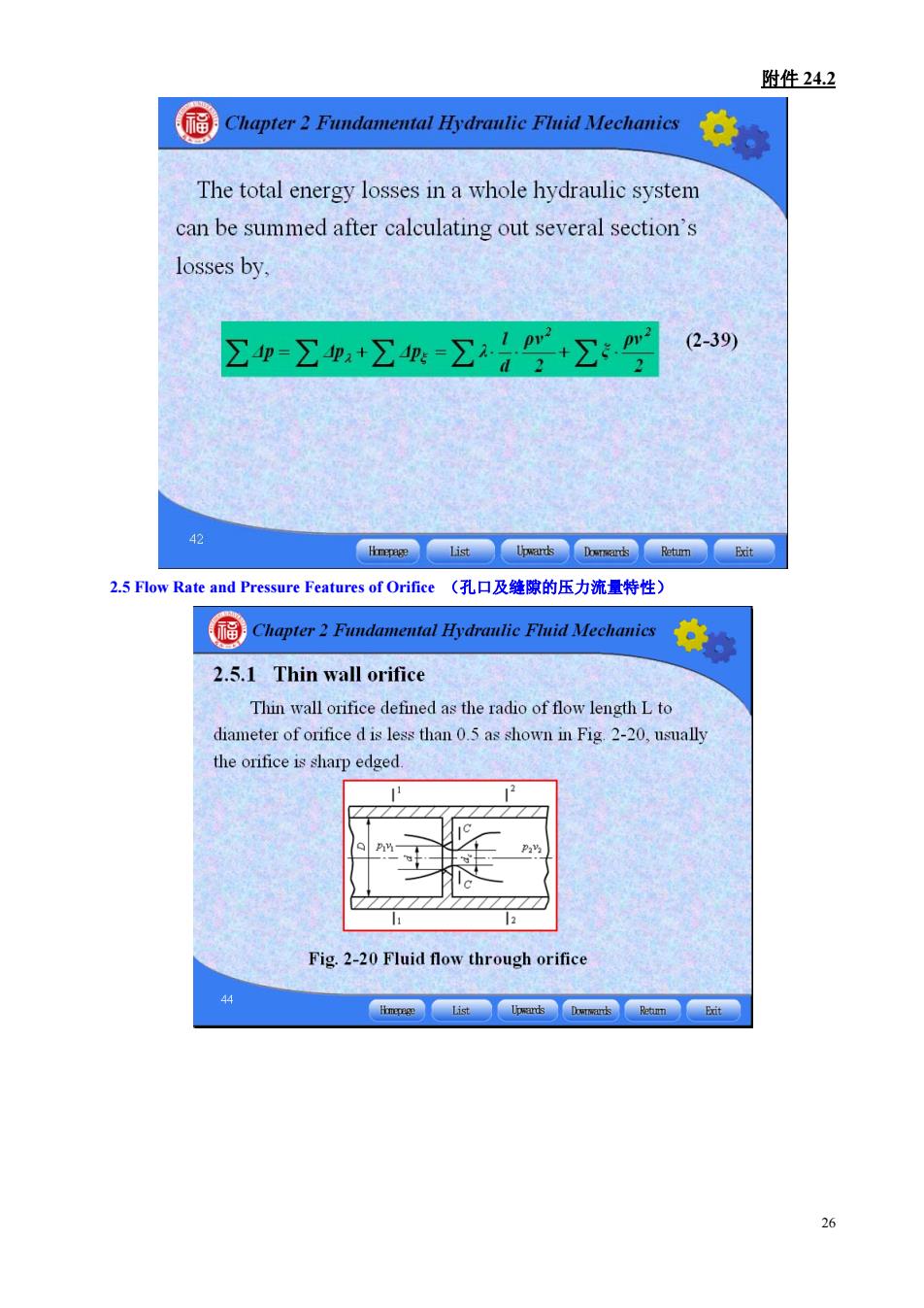
附件24.2 国Chapter2 eFd专。 The total energy losses in a whole hydraulic system can be summed after calculating out several section's losses by, 公p=∑p+工=公号学+公: (2-39) 2.5 Flow Rate and Pressure Features of Orifice(孔口及缝豫的压力流量特性) 2.5.1 Thin wall orifice Thin wall orifice defined as the radio of flow length L to diameter of orifice d is less than 0.5 as shown in Fig 2-20,nsually the orifice is sharp edged. Fig.2-20 Fluid flow through orifice
附件 24.2 26 2.5 Flow Rate and Pressure Features of Orifice (孔口及缝隙的压力流量特性)
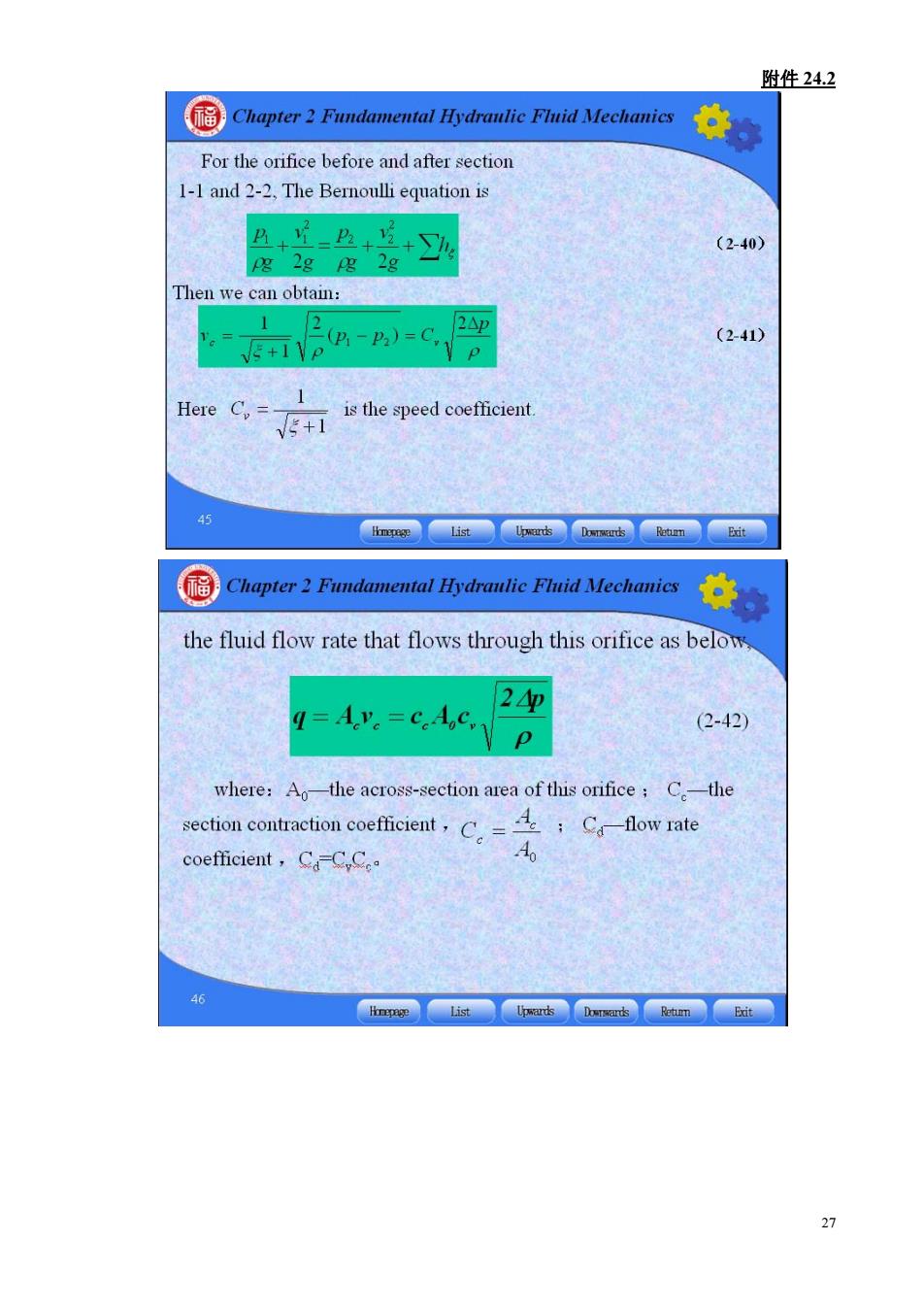
附件24.2 Chapter2 Fundamental Hydraulie Fhid Nechanies For the orifice before and after section 1-1 and 2-2,The Bernoulli equation is 凸++ (2-40) Pg 2g g 2g Then we can obtain: (P-P)-C. 2△p (2-41) Here C.=- is the speed coefficient. Chopter Fundamental Hydnalie Fid Nechanic the fluid flow rate that flows through this orifice as below Av.=.p 20 = (2-42) where:Ao-the across-section area of this orifice:C-the section contraction coefficient,Cflow rate coefficient,C-C,Ce A 6
附件 24.2 27
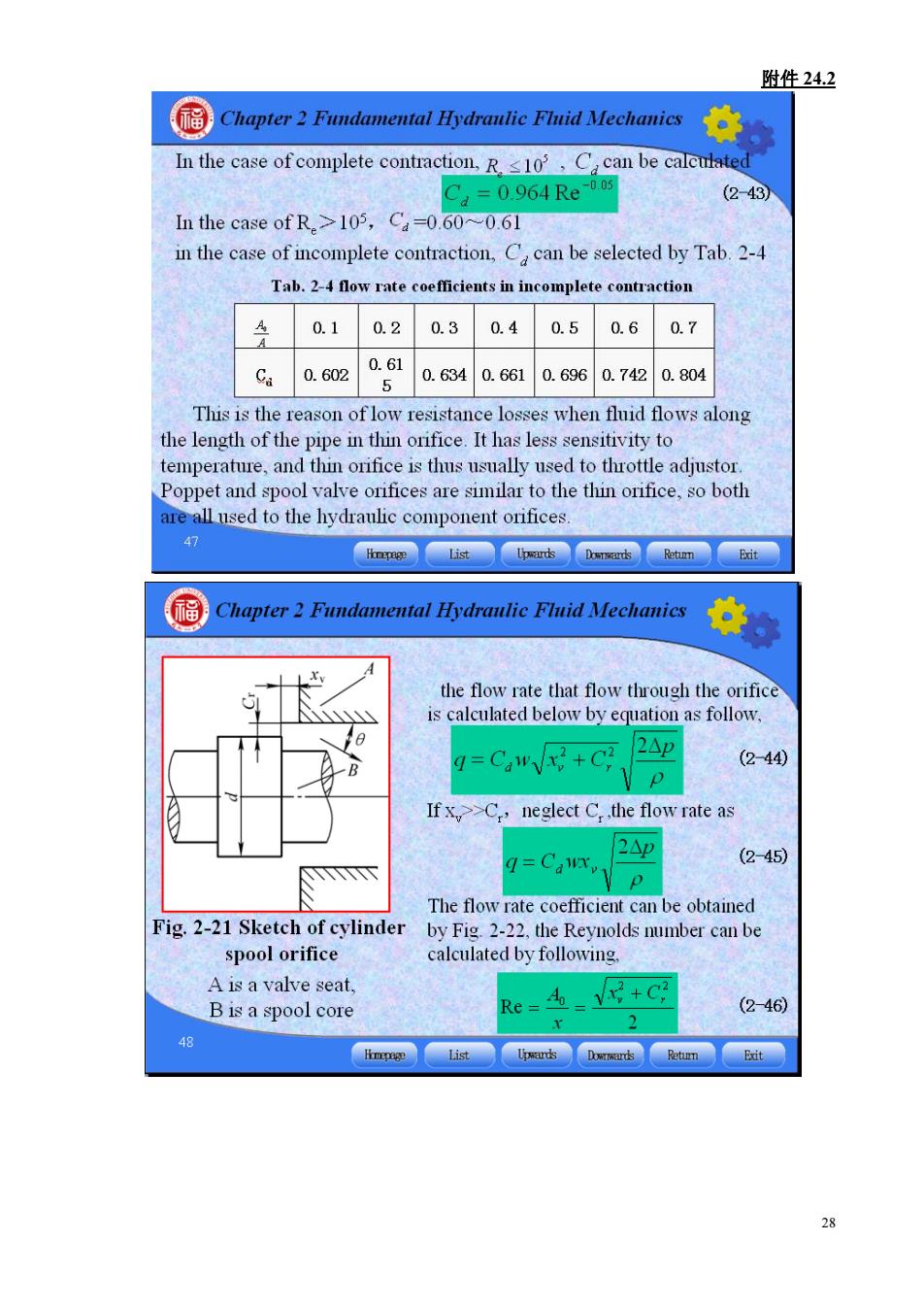
附件24.2 Chapter2 Fundamental Hydranlic Fluid Mechanics In the case of complete contraction.R1,C can be calcmate .=0064Re (2-43 In the case of R.>105,Ca=0.60~0.61 in the case of incomplete contraction,C can be selected by Tab.2-4 Tab.2-4 flow rate coefficients in incomplete contraction 40.10.20.30.40.50.60.7 c4062a61.634a.61a.660.7a804 This is the reason of low resistance losses when fluid flows along the lengh of the pipe n thin onifice It has less to temperature,and thin orifice is thus usually used to throttle adjustor. Poppet and spool valve orifices are similar to the thin orifice,so both e all used to the hydraulic component orifices. Chapter2 Fundamental Hydranlic Flnid Mechanies Xv the flow rate that flow through the orifice is calculated below by equation as follow. Caw+C 2△p (2-440 If xC,neglect C.the flow rate as 2△p (2-45) The flov can be obtained Fig.2-21 Sketch of cylinder by Fig 2-22.the Reynolds pmber can be spool orifice calculated by following. A is a valve seat. B is a spool core (2-46 2 28
附件 24.2 28