
附件242 2.3.3 Equation of momentum-conservation of momentum Fig.2-13 Sketch of oil flow through Fig.2-14 Sketch of oil fov a pipeline with a pressure vessel through a pipeline tem of above,the rate of chauge of nomentum in the system equals the net applie external force P=空 (220 The equation looks the same as the relationship Fig.2-15 Sketch of oi through curved passages F=Ma(221) Chapter2 Fundamental Hydranlic Flnid Nechanies a frictionles liquid in a ylindrical passage Fg2-14 92=4+6 (2-22) The force balance is,from equation (2-20): -pd- (2-23) cause g=dv.so (224
附件 24.2 19
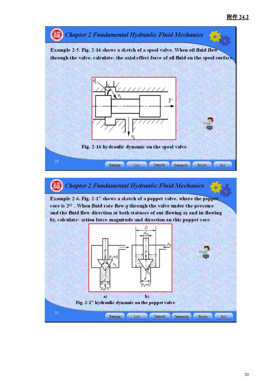
附件24.2 Chapter2 Fundamental Hydranlie Flnid Mechanies Example 2-5.Fig.2-16 shows a sketch of a spool valve.When oil fluid flow through the valve,calculate:the axial effect force of oil fuid on the spool surfac Fig.2-16 hydraulic dynamic on the spool valve Chapter2 Fundamental Hydranlic Flid Mechanics Example 2-6.Fig.2-17 shows a sketch of a poppet valve,where the poppet core is 2.When fluid rate flow g through the valve uder the pressure and the fluid flow direction at both statuses of out-flowing a)and in-flowing b),calculate:action force magnitude and direction on this poppet core. 20
附件 24.2 20
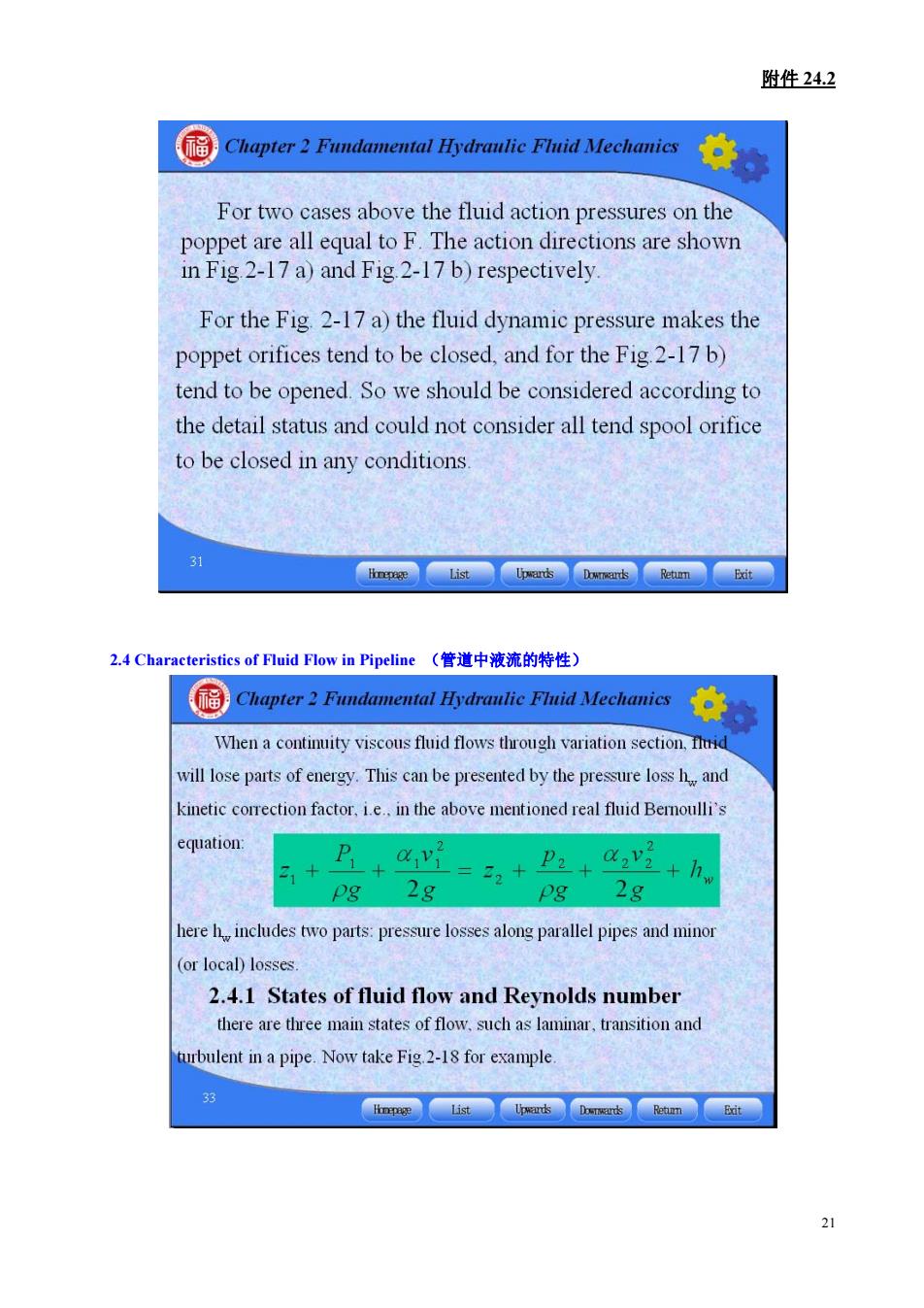
附件242 Chapter2 Fundamental Hydranlie Flnid Mechanies For two cases above the fluid action pressures on the poppet are all equal to F.The action directions are shown in Fig 2-17a)and Fig 2-17b)respectively. For the Fig 2-17 a)the fluid dynamic pressure makes the poppet orifices tend to be closed,and for the Fig 2-17 b) tend to be opened.So we should be considered according to the detail status and could not consider all tend spool orifice to be closed in any conditions. racteristicsof Fuid Flow in Pipeline(管道中液流的特性) 国Chopter2 Pndementol再drFidec年。 When a continuity viscous fluid flows through variation section,uid will lose parts of energy.This can be presented by the pressure loss h and kinetic correction factor,i.e.in the above mentioned real fluid Bemoulli's Pg 2g + +h, pg 2g here h includes two parts:pressure losses along parallel pipes and minor for local)losses. 2.4.1 States of fluid flow and Reynolds number there are three main states of flow.such as laminar,transition and rbulent in a pipe.Now take Fig 2-18 for example
附件 24.2 21 2.4 Characteristics of Fluid Flow in Pipeline (管道中液流的特性)
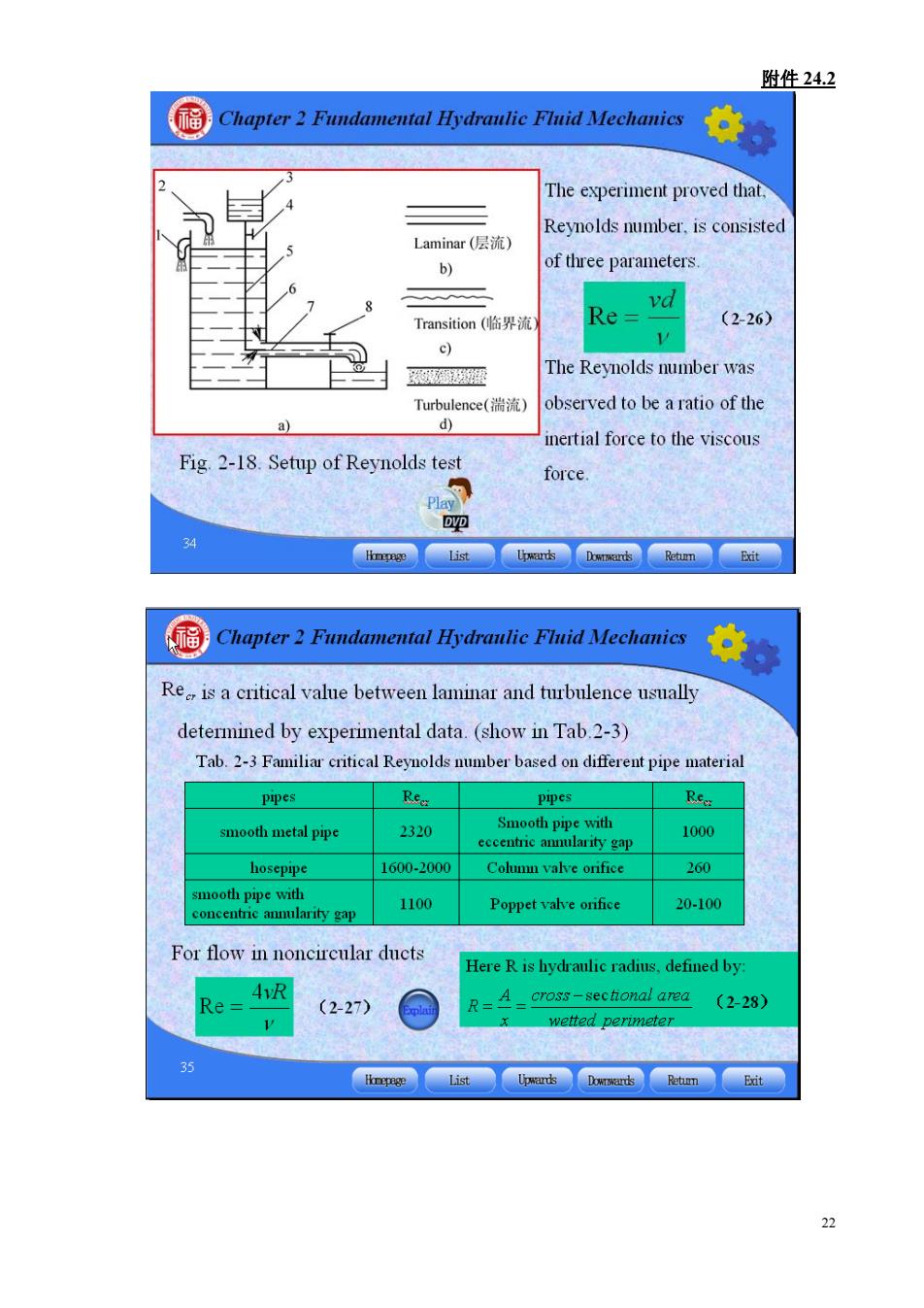
附件24.2 The experiment proved that Reynolds number.is consisted Laminar(层流) b) of three parameters vd Transition(临界流 Re= (2-26) c) 香 The Reynolds number was Turbulence(湍流 observed to be a ratio of the a) d) nertial force to the viscous Fig.2-18.Setup of Reynolds tes force. D吧 Bit Chapter2 Fundamental Hydranlic Flnid Mechanies Re is a critical value between laminar and turbulence usually determined by experimental data.(show in Tab.2-3) Tab.2-3 Familiar critical Reynolds number based on different pipe materia pipes pipes smooth metal pipe 2320 Smooth pipe with eccentric amnularity gap 1000 hosepipe 1600-2000 Cohuu valve orifice 260 1100 Poppet valve onfice 20-100 For flow in noncireular ducts Here R is hydraulic radius,defined by Re= (2-27) R=A=cross-sectonal area (2-28) g】
附件 24.2 22

附件24.2 Chapter2 Fundamental Hydranlic Flnid Mechanies 2.4.2 Losses along circle parallel pipe The losses due to viscosity in equal diameter pipe is referred as losses in parallel pipe,which will change with the different flowing states 1.Losses in parallel pipe at laminar flow (1)Velocity profile in a laminar pipe flow Fig.2-19 laminar flow in a circle pipe Chapter2 Fundamental Hydranlic Fluid Mechanies As show in Fig 2-19,a force balance in the x-direction yields,thus 1-2)m2=F,=-2ml du dr (229 Set△p=p1-P2 then: integrate it and under the boundary of u-0at R.we obtain, (R -x2) (2-30) 4ul It says that velocity profile in a laminar pipe flow along radi direction is a parabola R 23
附件 24.2 23