
附件24.2 For a hydraulic valve whatever flowing in or out,is the angle between streamline and spool line and is called speed direction angle, it is usually0=69° 4600.06010000 Fig.2-22 Flow coefficient on the orifice of spool valve 49 The poppet valve orifice is shown n Fig 2-23.When poppet movesupadis of x the average diameter of d =(d+d2)/2.=d,sina then the flow rate is 2=Ca.x,sm 24 (2-47) where the flow rate coefficient can be obtained by Fig.2-24 前 Fig.2-23 Orifice shape of Fig.2-24 Flow coefficient Co poppet valv 50 poppet valve orifice 29
附件 24.2 29
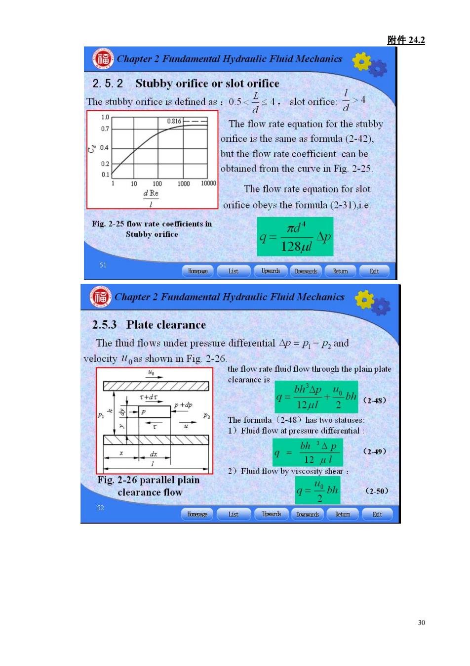
附件24.2 Chapter2 Fundamental Hydranlie Flnid Mechanies 2.5.2 Stubby orifice or slot orifice 1 The stubby onifice is defined asot ofce 0816 The flow rate equation for the stubby rifice is the same as formula (2-42). 90 but the flow rate coefficient can be btained from the curve in Fig.2-25 10 dRe The flow rate equation for slot orifice obeys the formula(2-31).i.e. d小 128d 2.5.3 Plate clearance The fluid flows under pressure differential Ap=p-p and velocity loas shown in Fig.2-26. the flow rate fluid flow trough the plain plate clearance is t+dt bhAp uobh (248) The formula (2-48)has two statuses 1)Fluid flow at pressure differential bh3△p (2-49) 12H/ 2)Fluid flow by viscosity shear Fig.2-26 parallel plain clearance flow q="obl (2-50) 52 30
附件 24.2 30
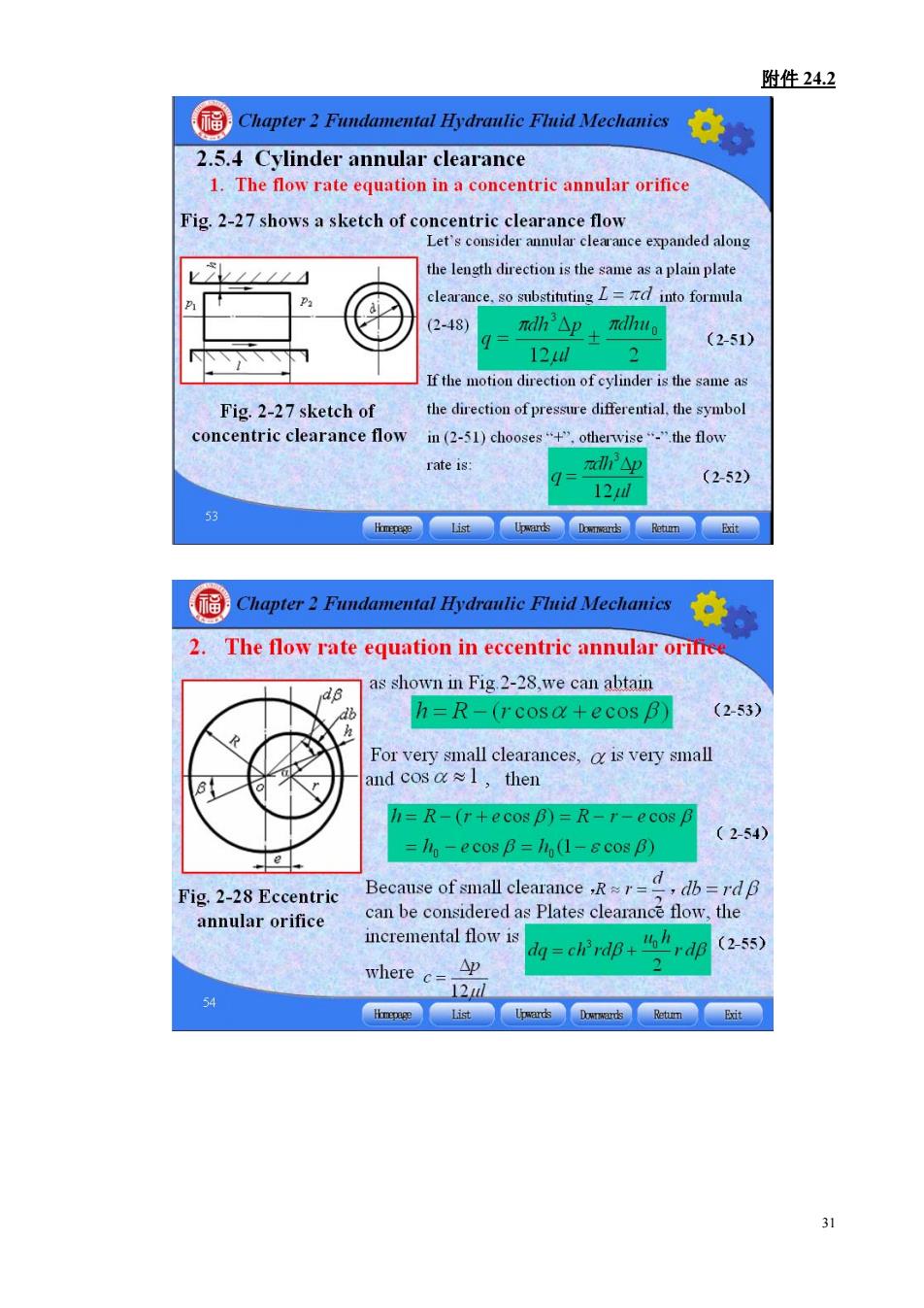
附件24.2 2.5.4 Cylinder annular clearance 1.The flow rate equation in a concentric annular orifice Fig.2-27 shows a sketch of concentric clearance flow Let's cousider annular expanded along the leugth direction is the same as a plain plate clearance.so ito formula (2-48) mdh△p+dh。 (2-51 12H If the motion direction of cylinder is the same as Fig.2-27 sketch of the direction of pressure differential,the symbol concentric clearance flow in(2-51)chooses+otherwise"the flow rate is: q- ah3△p (2-52) 12 Chapter2 Fundamental Hydranlic Flnid Mechanies 2.The flow rate equation in eccentric annular orifree as shown in Fig 2-28.we can abtain h=R-(rcosa+ecos B) (2-53) For very small clearances,o is very small and cosa≈l,then l=R-(r+ecos B)=R-r-ecos p =Iin-e cos B=It (1-&cos B) (2-54) Fig.2-28 Eccentric Because of small clearancerdp can be considered as Plates clearance flow,the annular orifice incremental flow is d西=chvd0+rdB2s) where c=12u △D
附件 24.2 31
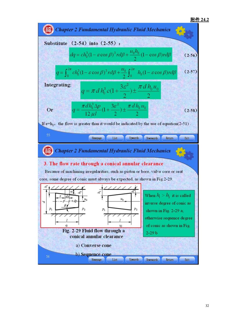
附件24.2 Substitute (2-54)into (2-55): g= ccopa-cos pyrdp (2-56 =cosB'rd 2J0 1i (1-s cos B)rdf (257) Integrating 9= πdhc+ 3e2 πdh" Or 124l 2 (2-58) 2 Ifthe flow than it would be indicated by the use of eqation(-51) 55 Chapter2 Fundamental Hydranlie Fluid Mechanies 3.The flow rate through a conical annular clearance Because of machining irregularities,such as piston or bore,valve core or seat re,some degree of always be expected.as Fig-29. When it is called mverse degree of conic as hown in Fig.2-29 a: herwise sequence degre of couic as shown i fig Fig.2-29 Fluid flow through a 2-29b conical annular clearance a)Converse cone b)Sequence come iis
附件 24.2 32

附件24.2 for the status of Fig 2-29 a,substituting into forula (2-51). (259 12 because:h-h+xtg 9,substituting dx= (2-59 dh 12ah6+dh tge h2 (2-60) Integrating and smbstitnting into 6 ndd (hh ) (2-61) We obtain the flow rate as. (h+h (2-62) 国 When =0,flow rate is nd ( 6W(h+24 (2-63 Integrating formula (2-61)the pressure distribution in this clearance flowing.and P=P πdgd h (2-64) 6() When u-0.we have + (2-65) 1-(2 1-2 P1- 1-色 (2-66) 33
附件 24.2 33