Chapter 7 Tractor's PTO System Section 2 PTO Device 1.2 Standard type PTO Shaft According to manipulation methods,PTO shafts can be divided into independent PTO shafts,semi-independent PTO shafts and dependent PTO shafts. Figure 7-7 Standard type PTO shaft 1.PTO shaft 2.Main clutch 3.2nd shaft of gearbox 械电子工程学酸 Automobile and Tractor Northwest A&F University
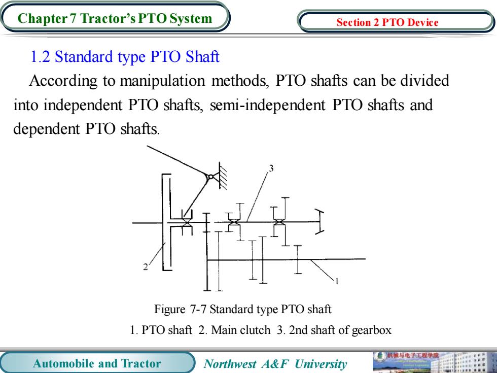
Automobile and Tractor Northwest A&F University Chapter 7 Tractor’s PTO System 1.2 Standard type PTO Shaft According to manipulation methods, PTO shafts can be divided into independent PTO shafts, semi-independent PTO shafts and dependent PTO shafts. Figure 7-7 Standard type PTO shaft 1. PTO shaft 2. Main clutch 3. 2nd shaft of gearbox Section 2 PTO Device
Chapter 7 Tractor's PTO System Section 2 PTO Device Figure 7-8 Semi-independent PTO shafts Figure 7-9 Independent PTO shafts 1.Ist shaft of transmission 2.Friction disc of 1.Main clutch 2.Friction disc of transmission 1st shaft 3.Clutch pedal auxiliary clutch 3.Auxiliary clutch 4.Friction disc of output shaft 5.Output shaft pedal 4.Main clutch pedal 5.Output shaft 机械与电子工程膜 Automobile and Tractor Northwest A&F University
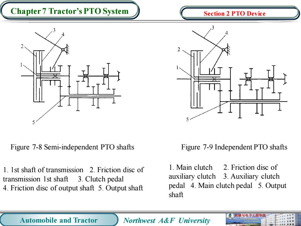
Automobile and Tractor Northwest A&F University Chapter 7 Tractor’s PTO System Figure 7-8 Semi-independent PTO shafts Figure 7-9 Independent PTO shafts 1. 1st shaft of transmission 2. Friction disc of transmission 1st shaft 3. Clutch pedal 4. Friction disc of output shaft 5. Output shaft 1. Main clutch 2. Friction disc of auxiliary clutch 3. Auxiliary clutch pedal 4. Main clutch pedal 5. Output shaft Section 2 PTO Device
Chapter 7 Tractor's PTO System Section 2 PTO Device 2.Power Take-off Belt Pulley (a)Receding side of belt on upside (b) Figure 7-10 Power take-off belt pulley (a)Postposition belt pulley (b)Right side belt pulley Automobile and Tractor Northwest A&F University
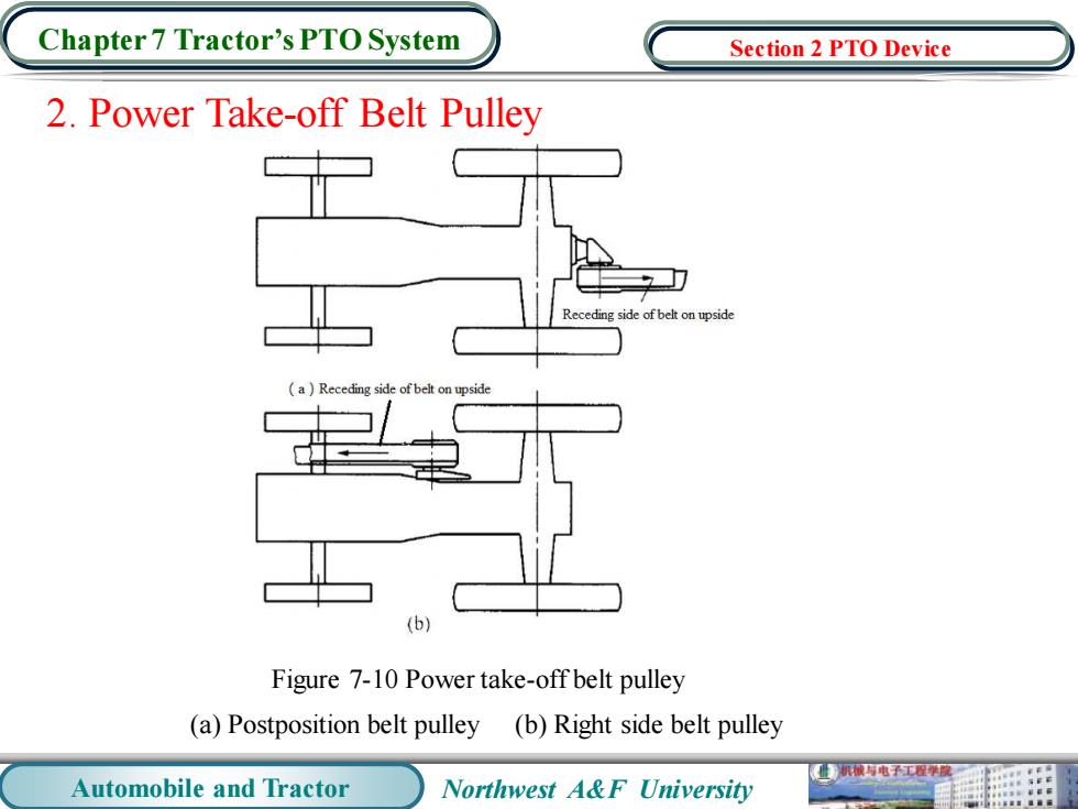
Automobile and Tractor Northwest A&F University Chapter 7 Tractor’s PTO System 2. Power Take-off Belt Pulley (a) Postposition belt pulley (b) Right side belt pulley Figure 7-10 Power take-off belt pulley Section 2 PTO Device
Chapter 7 Tractor's PTO System Section 2 PTO Device (a) (b) Figure 7-11 Diagram of changing rotation direction of belt pulley (a)Changing the position of driving bevel gear (b)Rotating the housing 180 1.PTO shaft 2.Housing 3.Driving bevel gear 4.Driven bevel gear 5.Belt pulley 机被寿电子工程原 Automobile and Tractor Northwest A&F University
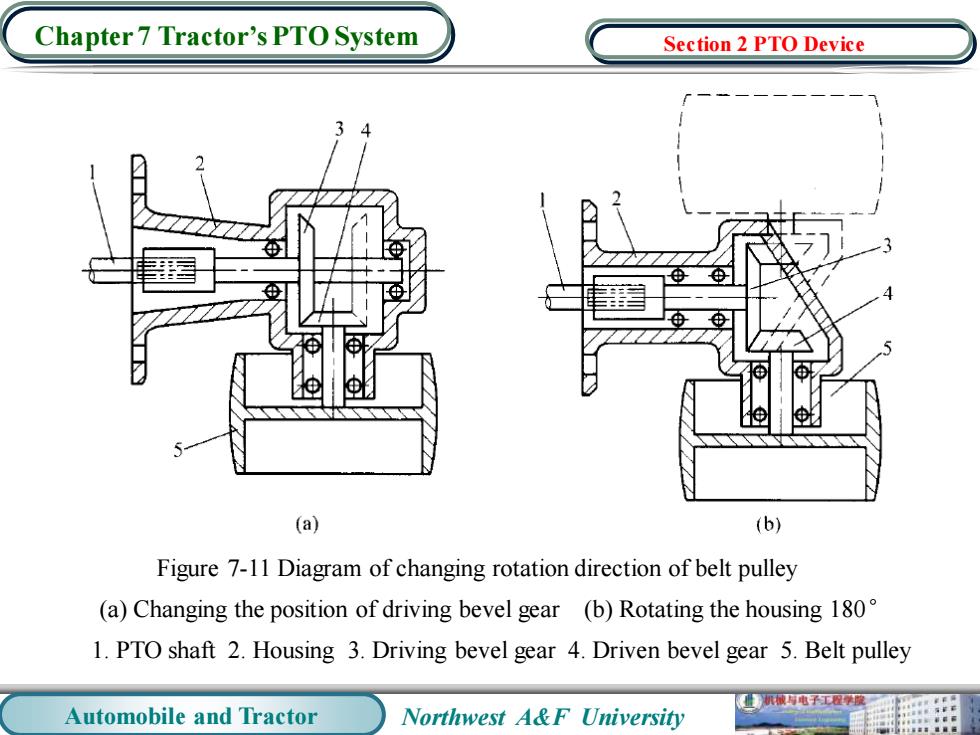
Automobile and Tractor Northwest A&F University Chapter 7 Tractor’s PTO System Figure 7-11 Diagram of changing rotation direction of belt pulley (a) Changing the position of driving bevel gear (b) Rotating the housing 180° 1. PTO shaft 2. Housing 3. Driving bevel gear 4. Driven bevel gear 5. Belt pulley Section 2 PTO Device
Chapter 7 Tractor's PTO System Section 3 Hydraulic Lift Hitch The devices using hydraulic to lift and control the farm machinery is called the hydraulic lift hitch.Its functions are as follows:connecting and towing the farm machinery,manipulating the upward and downward of farm machinery,controlling the tilth or hoisting height of the farm machinery,gaining weight to the driving wheels to improve the adhesion property and transmitting the hydraulic energy to the operating machinery for other operations. Hydraulic lift hitch is composed by the hydraulic system,control mechanism and suspension gear. 械电子工程学 Automobile and Tractor Northwest A&F University
Automobile and Tractor Northwest A&F University Chapter 7 Tractor’s PTO System The devices using hydraulic to lift and control the farm machinery is called the hydraulic lift hitch. Its functions are as follows: connecting and towing the farm machinery, manipulating the upward and downward of farm machinery, controlling the tilth or hoisting height of the farm machinery , gaining weight to the driving wheels to improve the adhesion property and transmitting the hydraulic energy to the operating machinery for other operations. Hydraulic lift hitch is composed by the hydraulic system, control mechanism and suspension gear. Section 3 Hydraulic Lift Hitch