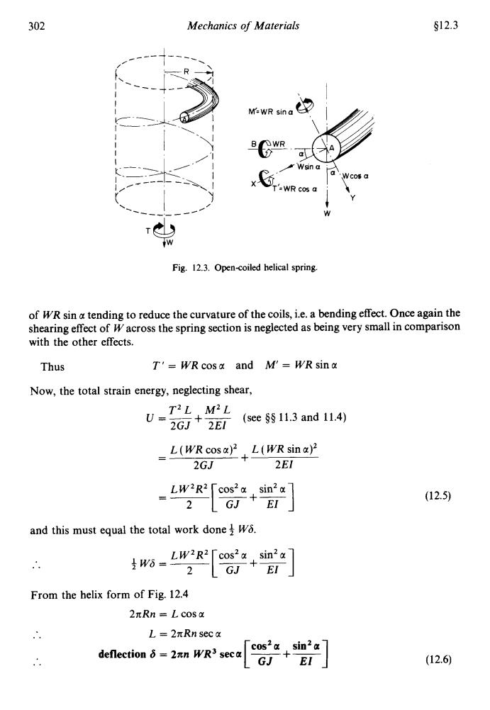
302 Mechanics of Materials §12.3 M-WR sina A a Wsin a x a Wcos a T'=WR cos a Fig.12.3.Open-coiled helical spring. of WR sin a tending to reduce the curvature of the coils,i.e.a bending effect.Once again the shearing effect of W across the spring section is neglected as being very small in comparison with the other effects. Thus T'=WR cosa and M'=WR sina Now,the total strain energy,neglecting shear, T2L M2L U=2GJ+2EI (see $11.3 and 11.4) =L(WR cosa)L(WR sina) 2GJ 2EI (12.5) and this must equal the total work done W. ww[2+] From the helix form of Fig.12.4 2πRn=Lcosa L=2πRn sec a cos2a sin2a deflection 8=2an WR3 seca G+ (12.6)
302 Mechanics of Materials $12.3 1’ W Fig. 12.3. Opencoiled helical spring. of WR sin u tending to reduce the curvature of the coils, i.e. a bending effect. Once again the shearing effect of W across the spring section is neglected as being very small in comparison with the other effects. Thus T’ = WRcosa and M = WRsina Now, the total strain energy, neglecting shear, u=-- *’ +- M2 (see $5 11.3 and 11.4) 2GJ 2EI L ( WR cos a)’ 2GJ L ( WR sin a)2 - -I 2EI LW‘R’ cosza sin’a - --[-+-I 2 GJ EI and this must equal the total work done $ W6. .. 2 [ GJ +I] From the helix form of Fig. 12.4 LW~R’ cos2u sin’u $WS=- __ 2nRn = L cos a .. L = 2nRn sec u [ cos’a ~ sin2a] .. deflection S = 2an WR3 seca - GJ EI (12.5) (12.6)
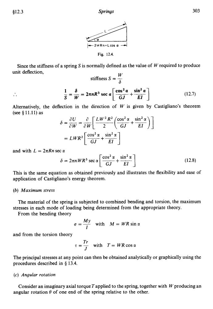
§12.3 Springs 303 ◆-2TRn=Lc05a Fig12.4. Since the stiffness of a spring S is normally defined as the value of W required to produce unit deflection, stiffness W S=W=2πnR3seca 16 cos2a sin2a GJ+ 十 (12.7) EI Alternatively,the deflection in the direction of w is given by Castigliano's theorem (see§11.11)as aU 8= =LWR2 cos2 a sin2 GJ +EI and with L=2πRn sec a 6=2πnWR3sec [+] (12.8) This is the same equation as obtained previously and illustrates the flexibility and ease of application of Castigliano's energy theorem. (b)Maximum stress The material of the spring is subjected to combined bending and torsion,the maximum stresses in each mode of loading being determined from the appropriate theory. From the bending theory My 0= with M=WR sin a and from the torsion theory Tr with T=WR cosa The principal stresses at any point can then be obtained analytically or graphically using the procedures described in 13.4. (c)Angular rotation Consider an imaginary axial torque Tapplied to the spring,together with W producing an angular rotation of one end of the spring relative to the other
$12.3 Springs 303 +2nRn=Lcos a ---/ Fig. 12.4. . .. Since the stiffness of a spring S is normally defined as the value of --’ w requirea to proauce W stiffness S = - 6 unit deflection, .. - 16 = - = 2nnR3 sec a [‘e+-] sin2 a sw GJ EZ Alternatively, the deflection in the direction of W is given by (see $ 11.11) as au a LW~R~ cos2a sin’a 6=--=-. ___ aw aw[ 2 (r+r)] = LWRz[--Gj-+y] cosza sin’u and with L = 2nRn sec CI cos’a sin’cc 6 = 2nn WR3 sec a (1 2.7) Castigliano’s theorem (12.8) This is the same equation as obtained previously and illustrates the flexibility and ease of application of Castigliano’s energy theorem. (b) Maximum stress The material of the spring is subjected to combined bending and torsion, the maximum From the bending theory stresses in each mode of loading being determined from the appropriate theory. MY I 0 = - with M = WRsina and from the torsion theory Tr J 5 = - with T = WRcosa The principal stresses at any point can then be obtained analytically or graphically using the procedures described in Q 13.4. (c) Angular rotation Consider an imaginary axial torque Tapplied to the spring, together with W producing an angular rotation 8 of one end of the spring relative to the other
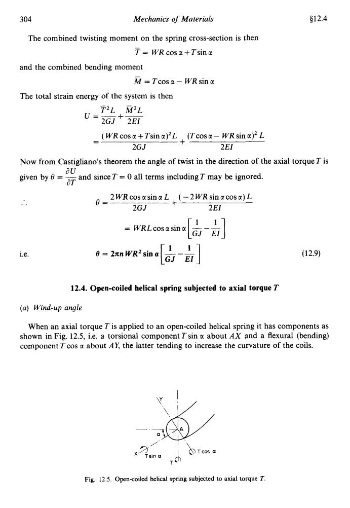
304 Mechanics of Materials §12.4 The combined twisting moment on the spring cross-section is then T=WR cosa+Tsin a and the combined bending moment M=Tcos a-WR sin a The total strain energy of the system is then T2L M2L U=2GJ2EI (WR cosa+Tsin )L (Tcosa-WR sin)L 2GJ 2EI Now from Castigliano's theorem the angle of twist in the direction of the axial torque T is aU given bynd sinceTall terms includingTmay be ord. 02WR cos asinaL(-2WR sin acosa)L 2GJ 2EI 「11 =WRLcosa sina 0=2πnWR2sina 117 i.e. GJEI」 (12.9) 12.4.Open-coiled helical spring subjected to axial torque T (a)Wind-up angle When an axial torque T is applied to an open-coiled helical spring it has components as shown in Fig.12.5,i.e.a torsional component T sin g about AX and a flexural (bending) component T cos a about AY,the latter tending to increase the curvature of the coils. ①Tcos a Tsin a Fig.12.5.Open-coiled helical spring subjected to axial torque T
304 Mechanics of Materials $12.4 The combined twisting moment on the spring cross-section is then - T= WRcosu+Tsinu and the combined bending moment M =Tcosu- WRsinu The total strain energy of the system is then - - T~L M~L u=-- +- 2GJ 2EI ( WR cos u + Tsin u)’L 2GJ (Tcos u - WR sin u)’ L 2EI + - Now from Castigliano’s theorem the angle of twist in the direction of the axial torque T is given by 0 = - and since T = 0 all terms including T may be ignored. au aT .. i.e. 2WRcosusinuL (-2WRsinucosa)L 2EI + 2GJ e= = WRLcosusinu --- [iJ ;I] 0 = 2xnWR’sina [A A] ( 12.9) 12.4. Open-coiled helical spring subjected to axial torque T (a) Wind-up angle When an axial torque Tis applied to an open-coiled helical spring it has components as shown in Fig. 12.5, i.e. a torsional component T sin u about AX and a flexural (bending) component T cos u about AY the latter tending to increase the curvature of the coils. Fig, 12.5. Opencoiled helical spring subjected to axial torque T
s12.5 Springs 305 As for the close-coiled spring the total strain energy is given by strain energy U=GJ2EI T2L M2L =L(T'sin2+Tcosa)‖ GJ T2L「sin2x,cos2x 2GJ EI (12.10) and this is equal to the work done by T,namely,T0,where 0 is the angle turned through by one end relative to the other,i.e.the wind-up angle of the spring. 70=T2L and,with L =2Rn sec a as before, wind-up angle 0=2mnRT sec a sin2 a cos2a GJ+EI (12.11) (b)Maximum stress The maximum stress in the spring material will be found by the procedure outlined in 12.3(b)with a bending moment of T'cos a and a torque of T sin a applied to the section. (c)Axial defection Assuming an imaginary axial load W applied to the spring the total strain energy is given by eqn.(11.5)as U=(WRcos+Tsin a)L (Tcosa-WRsina)L 2GJ 2EI Now from Castigliano's theorem the deflection in the direction of W is given by 6= aU ow 「1 =TRLcos a sin GJEI when W=0 deflection 8=2anTR2 sin a 11 GJ EI (12.12) 12.5.Springs in series If two springs of different stiffness are joined end-on and carry a common load W,they are said to be connected in series and the combined stiffness and deflection are given by the following equations
412.5 Springs 305 As for the close-coiled spring the total strain energy is given by T~L M~L strain energy U = __ +- 2GJ 2EI (1 2.10) 1 (Tsinu)’ (TCOS~)~ El + and this is equal to the work done by T, namely, 4 TQ, where 6 is the angle turned through by one end relative to the other, i.e. the wind-up angle of the spring. iTQ =fT2L[7+EI] sin’a cos2 a and, with L = 2zRn sec a as before, sinZa cos’a wind-up angle 0 = 2anRTsec a (12.11) (b) Maximum stress The maximum stress in the spring material will be found by the procedure outlined in tj 12.3(b) with a bending moment of Tcos u and a torque of T sin a applied to the section. (c) Axial deflection Assuming an imaginary axial load W applied to the spring the total strain energy is given by eqn. (1 1.5) as ( WR cos a + Tsin u)’L 2GJ (Tcos u - WR sin a)’ L 2EI U= + Now from Castigliano’s theorem the deflection in the direction of W is given by au aw a=-- =TRLcosusina [jJ --- d,] when W=O deflection 6 = 2xnTR’sin a - - - [iJ A] 12.5. Springs in series (1 2.12) If two springs of different stiffness are joined end-on and carry a common load W, they are said to be connected in series and the combined stiffness and deflection are given by the following equations
306 Mechanics of Materials 12.6 W WW Deflection =+a 117 -W Ls+s」 (12.13) 11.1 ss+52 and stiffness S= SiS2 (12.14) S1+S2 12.6.Springs in parallel If two springs are joined in such a way that they have a common deflection o they are said to be connected in parallel.In this case the load carried is shared between the two springs and total load W=W1+W2 (1) Now wW W2 8= S-S S (12.15) so that =Sw S2W S and W2= Substituting in eqn.(1) W=SW S2W S+ S W「 9+, i.e. combined stiffness S=S+S2 (12.16) 12.7.Limitations of the simple theory Whilst the simple torsion theory can be applied successfully to bars with small curvature without significant error the theory becomes progressively more inappropriate as the curvatures increase and become high as in most helical springs.The stress and deflection equations derived in the preceding sections,are,therefore,slightly inaccurate in practice, particularly for small D/d ratios.For accurate assessment of stresses and deflections account should be taken of the infuence of curvature and slope by applying factors due to Wahlt and Ancker and Goodiert.These are discussed in Roark and Young$where the more accurate tA.M.Wahl,Mechanical Springs,2nd edn.(McGraw-Hill,New York 1963). C.J.Ancker (Jr)and J.N.Goodier,"Pitch and curvature correction for helical springs",ASME J.Appl.Mech.. 25(4).Dec.1958. $R.J.Roark and W.C.Young.Formulas for Stress and Strain,5th edn.(McGraw-Hill,Kogakusha,1965)
306 Mechanics of Materials $12.6 .. and W ww Deflection = - = 6, +6, = -+- S Sl s2 =w -+- a 111 _- +- s-s, s, SlS, Sl + sz stiffness S = ~ (12.1 3) (1 2.14) 12.6. Springs in parallel If two springs are joined in such a way that they have a common deflection 6 they are said to be connected in parallel. In this case the load carried is shared between the two springs and total load W = W, + W, (1) Now so that Substituting in eqn. (1) i.e. SlW and W, = - s2w S w, =- S s,w s2w W=-- +- S S =‘Y[s,+s,] S combined stiffness S = S, + Sz (12.15) (1 2.16) 12.7. Limitations of the simple theory Whilst the simple torsion theory can be applied successfully to bars with small curvature without significant error the theory becomes progressively more inappropriate as the curvatures increase and become high as in most helical springs. The stress and deflection equations derived in the preceding sections, are, therefore, slightly inaccurate in practice, particularly for small D/d ratios. For accurate assessment of stresses and deflections account should be taken of the influence of curvature and slope by applying factors due to Wahlt and Ancker and GoodierS. These are discussed in Roark and Young§ where the more accurate t A. M. Wahl, Mechanical Springs, 2nd edn. (McGraw-Hill, New York 1963). $ C. J. Ancker (Jr) and J. N. Goodier, “Pitch and curvature correction for helical springs”, ASME J, Appl. Mech., 25(4), Dec. 1958. R. J. Roark and W. C. Young, Formulasfor Stress and Strain, 5th edn. (McGraw-Hill, Kogakusha, 1965)