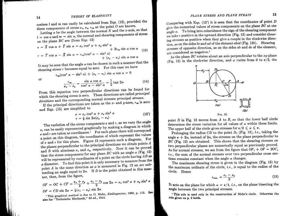
15 14 THEORY OF ELASTICITY PLANE STRESS AND PLANE STRAIN cosines l and m can easily be calculated from Eqs.(12),provided the Comparing with Eqs.(13)it is seen that the coordinates of point D three components of stress at the point 0 are known. give the numerical values of stress components on the plane BC at the Letting a be the angle between the normal N and the z-axis,so that angle To bring into coineidence the sign of the shearing component I cos a and m=sin @the normal and shearing components of stress we taker positive in the upward direction (Fig.13)and consider shear. on the plane BC are (from Eqs.12) ing stresses as positive when they give a couple in the clockwise direc- G&cos a P sin a os cos2 a+y sin a tion,as on the sides bc and ad of the element abed (Fig.136).Shearing 2rsy sin a cos a (13) stresses of opposite direction,as on the sides ab and de of the element, =cos a-&sin a Ta(cos2 a Bin2 a) are considered as negative.1 +(-=sin a cos a As the plane BC rotates about an axis perpendicular to the zy-plane It may be seen that the angle a can be chosen in such a manner that the (Fig.12)in the clockwise direction,and a varies from 0 to r/2,the shearing stress r becomes equal to zero.For this case we have Tay(cos*a -sin2 a)+(-=sin a cos a=0 or sin a cos a cog a sini a tan 2a (14) From this equation two perpendicular directions can be found for which the shearing stress is zero.These directions are called principal directions and the corresponding normal stresses principal stresses. If the principal directions are taken as the z-and y-axes,is zero a and Egs.(13)are simplified to =Ga cos2 a gy sin2 a (13) FiG.13. T=黄sin2x(ay-o) The variation of the stress components and r,as we vary the angle point D in Fig.13 moves from A to B,so that the lower half circle a,can be easily represented graphically by making a diagram in which determines the stress variation for all values of a within these limits. o andr are taken as coordinates.For each plane there will correspond The upper half of the circle gives stresses for /2 a $ a point on this diagram,the coordinates of which represent the values Prolonging the radius CD to the point D(Fig.13),i.e.,taking the of o and r for this plane.Figure 13 represents such a diagram.For angle +2a,instead of 2a,the stresses on the plane perpendicular to BC (Fig.12)are obtained.This shows that the shearing stresses on the planes perpendicular to the principal directions we obtain points A and B with abscissas s and respectively.Now it can be proved two perpendicular planes are numerically equal as previously proved. that the stress components for any plane BC with an angle a(Fig.12) As for normal stresses,we see from the figure that OF:+OF =20C, will be represented by coordinates of a point on the circle having AB as i.e.,the sum of the normal stresses over two perpendicular cross sec- tions remains constant when the angle a changes. a diameter.To find this point it is only necessary to measure from the point A in the same direction as a is measured in Fig.12 an are sub- The maximum shearing stress is given in the diagram (Fig.13)by tending an angle equal to 20.If D is the point obtained in this man- the maximum ordinate of the circle,i.e.,is equal to the radius of the circle.Hence ner,then,from the figure, Tma.=Js-dy (15) 2 OF OC+CP c08 2a-o cosasin a 2 It acts on the plane for which /4,i.e.,on the plane bisecting the DF CD sin 2a =(=-ou)sin 2a angle between the two principal stresses. This graphical method is due to O.Mohr,Zivilingenieur,1882,p.113.See This rule is used only in the construction of Mohr's eirele.Otherwise the also his "Technische Mechanik,"2d ed.,1914. rule given on p.3 holds
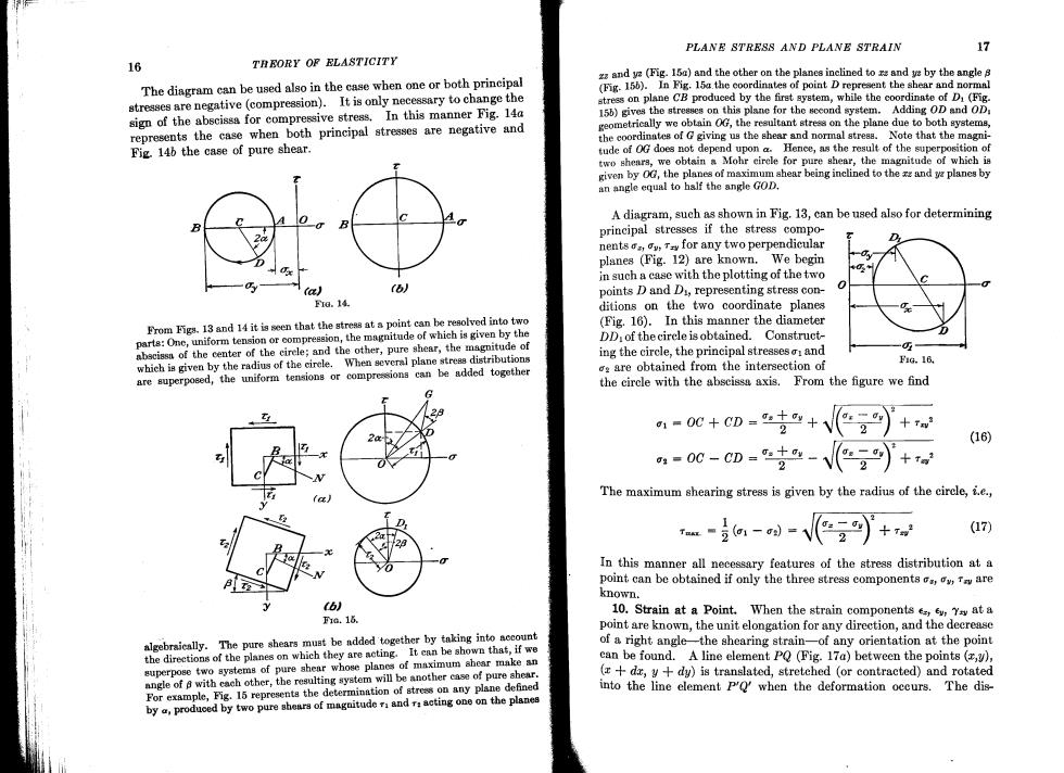
PLANE STRESS AND PLANE STRAIN 17 16 TREORY OF ELASTICITY zand y(Fig.15)and the other on the planes inclined to rsand y by the angle 8 The diagram can be used also in the case when one or both principal (Fig.156).In Fig.15a the coordinates of point D represent the shear and normal stresses are negative(compression).It is only necessary to change the stress on plane CB produced by the firet system,while the coordinate of D(Fig. sign of the abscissa for compressive stress.In this manner Fig.14a 156)gives the stresses on this plane for the sccond system.Adding OD and OD represents the case when both principal stresses are negative and geometrically we obtain G,the resultant stress on the plane due to both ayster, the coordinates of G giving us the shear and normal stresa.Note that the magni- Fig.146 the case of pure shear. tude of 0G does not depend upon a Henee,as the result of the superposition of two sheara,we obtain a Mohr eircle for pure shear,the magnitude of which is given by 0G,the planes of maximum shear being inclined to the and yplanes by an angle equal to half the angle GOD. A diagram,such as shown in Fig.13,can be used also for determining principal stresses if the stress compo- nentsv,for any two perpendicular planes (Fig.12)are known. We begin in such a case with the plotting of the two (a) 6) points D and D,representing stress con- Fra.14. ditions on the two coordinate planes From Figs.13 and 14 it is seen that the stress at a point can be resolved into two (Fig.16).In this manner the diameter parts:One,uniform tension or compression,the magnitude of which is given by the DD,of the circle is obtained. Construct- abscissa of the center of the cirele;and the other,pure shear,the magnitude of ing the circle,the principal stresses and which is given by the radius of the cirele.When several plane streas distributions are superposed,the uniform tensions or compressions can be added together are obtained from the intersection of F1G.16 the circle with the abscissa axis.From the figure we find ,-0C+c-+2) 2 十7w (16) 4=00-CD=4- 2 The maximum shearing stress is given by the radius of the circle,i.e., 1 (17) In this manner all necessary features of the stress distribution at a point can be obtained if only the three stress components,r are known. (6) 10.Strain at a Point.When the strain components e ev,Ys at a F1.16. point are known,the unit elongation for any direction,and the decrease algebraically.The pure shears must be added together by taking into account of a right angle-the shearing strain-of any orientation at the point the directions of the planes on which they are acting.It can be shown that,if we superpose two systems of pure shear whose planes of maximum ahear make an can be found.A line element PQ (Fig.17a)between the points (,) angle of a with cach other,the resulting system will be another case of pure shear. (r+dr,y+dy)is translated,stretched (or contracted)and rotated For example,Fig.15 represents the determination of stress on any plane defined into the line element P'Q'when the deformation occurs.The dis- by,produced by two pure shears of magnitude andr acting one on the planes
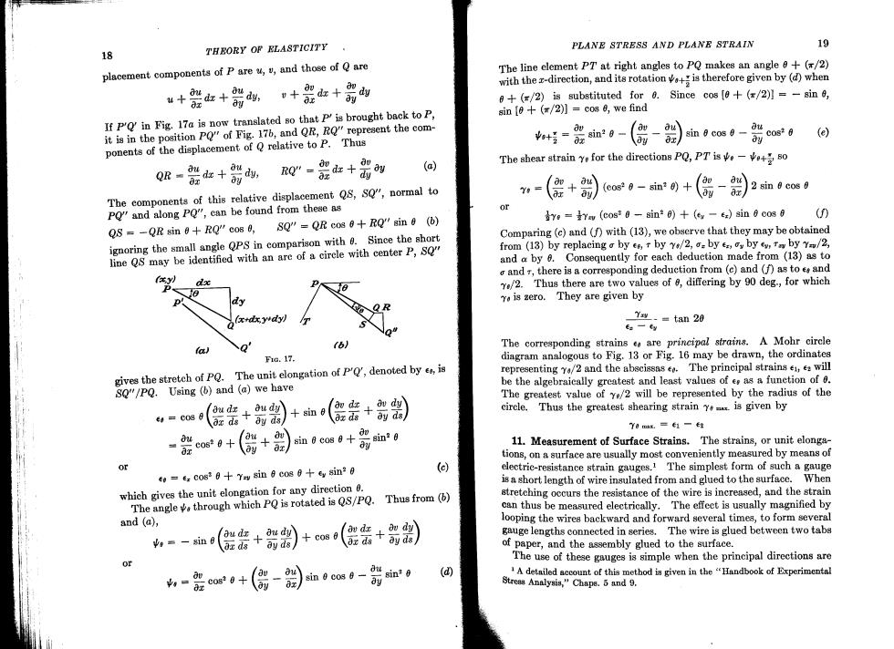
PLANE STRESS AND PLANE STRAIN 19 18 THEORY OF ELASTICITY placement components of P are u,v,and those of Q are The line element PT at right angles to PQ makes an angle +(/2) with the x-direction,and its rotationis therefore given by(d)when +器女+,+显红+岛的 +(=/2)is substituted for 0.Since cos [0+(/2)]=-sin 0, If P'Q'in Fig.17a is now translated so that P'is brought back to P, sin [+(/2)]cos e,we find it is in the position PQ"of Fig.176,and QR,RQ"represent the com- sin 8 cos 0- ou cos*0 (e) ponents of the displacement of Q relative to P.Thus ay Q吸-能+箭-是山+器 The shear strain ye for the directions PQ,PTis80 0x (a) The components of this relative displacement Q8,SQ",normal to n-(+cas0-m+(- )2 sin 0 cos 0 PQ"and along PQ",can be found from these as ye =Yev (cos2 0-sin0)+(ex-ez)sin 6 cos 8 () QS =-QR sin 0+RQ"cos 0, SQ"=QR cos 0+RQ"sin 0 ( ignoring the small angle QPS in comparison with 0.Since the short Comparing (c)and (f)with(13),we observe that they may be obtained line QS may be identified with an are of a cirele with center P,SQ" from (13)by replacing a by es,t by Y4/2,by e,y by e,Tn by Y/2, and a by 6.Consequently for each deduction made from (13)as to o and 7,there is a corresponding deduction from (c)and (f)as to e and dx /2.Thus there are two values of 8,differing by 90 deg,for which Yo is zero.They are given by Ys-=tan 20 E:-ty r6. The corresponding strains ee are principal strains.A Mohr circle a F1.17. diagram analogous to Fig.13 or Fig.16 may be drawn,the ordinates gives the stretch of PQ.The unit elongation of P,denoted by e,is representing Y/2 and the abscissas e.The principal strains ,e will SQ"/PQ.Using (b)and (a)we have be the algebraically greatest and least values of e as a funetion of 0. The greatest value of ye/2 will be represented by the radius of the (密+ 】+sin circle.Thus the greatest shearing strain Y is given by Y0mx.=1一eg d cos*0+ au sin 0 cos 防in*g 11.Measurement of Surface Strains.The strains,or unit elonga- tions,on a surface are usually most conveniently measured by means of or ee=ez cos3 0++Yay sin 6 cos ey sin20 (e) electric-resistance strain gauges.1 The simplest form of such a gauge is a short length of wire insulated from and glued to the surface.When which gives the unit elongation for any direction 0. Thus from (b) stretching occurs the resistance of the wire is increased,and the strain The angle through which PQ is rotated is QS/PQ. can thus be measured electrically.The effect is usually magnified by and (a), looping the wires backward and forward several times,to form several ou dy dv dx gauge lengths connected in series.The wire is glued between two tabs s=-sin +cos 0 ay ds ox ds of paper,and the assembly glued to the surface. The use of these gauges is simple when the principal directions are -+(偶- sin 0 cos 6- (d) A detniled account of this method is given in the "Handbook of Experimental Streas Analysis,"Chaps.5 and 9
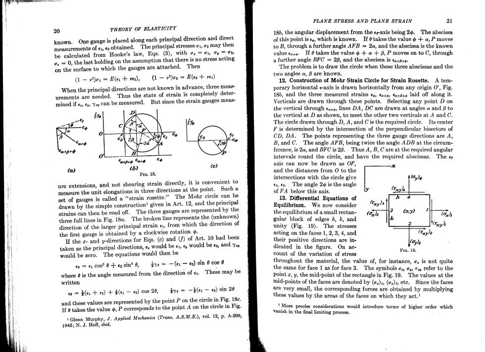
PLANE STRESS AND PLANE STRAIN 21 20 THEORY OF ELASTICITY 186,the angular displacement from the ee-axis being 20.The abscissa known.One gauge is placed along each principal direction and direct of this point is e,which is known.If takes the value+a,P moves measurements of,obtained.The principal stresses may then to B,through a further angle AFB 20,and the abscissa is the known be calculated from Hooke's law,Eqs.(3),with o==1,o value ca+,If&takes the value中+&+月,P moves on to c,through =0,the last holding on the assumption that there is no stress acting a further angle BFC =28,and the abscissa is on the surface to which the gauges are attached.Then The problem is to draw the circle when these three abscissas and the (1-2)o1=E(e1十e,(1-)o=E(e+e two angles a,B are known. 12.Construction of Mohr Strain Circle for Strain Rosette.A tem- When the principal directions are not known in advance,three meas- porary horizontal e-axis is drawn horizontally from any origin O',Fig. urements are needed.Thus the state of strain is completely deter- 18b,and the three measured strainslaid off along it. mined ifY can be measured. But since the strain gauges meas- Verticals are drawn through these points.Selecting any point D on the vertical through lines DA,DC are drawn at angles a and 8 to the vertical at D as shown,to meet the other two verticals at A and C. The circle drawn through D,A,and C is the required circle.Its center F is determined by the intersection of the perpendicular bisectors of CD,DA.The points representing the three gauge directions are A, B,and C.The angle AFB,being twice the angle ADB at the circum- ference,is 2a,and BFC is 28.Thus A,B,C are at the required angular B intervals round the circle,and have the required abscissas. The ce 气xp+p6a+g (6) (c) axis can now be drawn as OF, (a) Fa,18 and the distances from 0 to the intersections with the circle give ure extensions,and not shearing strain direetly,it is convenient to ,e.The angle 2 is the angle measure the unit elongations in three directions at the point.Such a of FA below this axis. set of gauges is called a "strain rosette."The Mohr cirele can be 13.Differential Equations of drawn by the simple constructionl given in Art.12,and the principal Equilibrium.We now consider (Ezy/3 strains can then be read off.The three gauges are represented by the the equilibrium of a small rectan- three full lines in Fig.18a.The broken line represents the (unknown) gular block of edges h,k,and direction of the larger principal strain e from which the direction of unity (Fig.19).The stresses the first gauge is obtained by a clockwise rotation acting on the faces 1,2,3,4,and (txy If the x-and y-directions for Eqs.(c)and (f)of Art.10 had been their positive directions are in- taken as the prineipal directions,e would bewould be e andY dicated in the figure.On ac- h would be zero.The equations would then be Fto.19. count of the variation of stress eo=e1 cos2 6+ea sin0,-(e:-ea)sin 6 cos 0 throughout the material,the value of,for instance,is not quite where is the angle measured from the direction of e.These may be the same for face 1 as for face 3.The symbolsv,refer to the point z,y,the mid-point of the rectangle in Fig.19.The values at the written mid-points of the faces are denoted by ()()a,ete.Since the faces =(e+)十(e1-)c0s20,ye=-(e1-)in20 are very small,the corresponding forces are obtained by multiplying and these values are represented by the point P on the cirele in Fig.18c. these values by the areas of the faces on which they act. If takes the value P corresponds to the point A on the circle in Fig. More precise considerations would introduce terms of higher order which Glenn Murphy,J.Applied Mechanics (Trans.A.S.M.B.),vol.12,p.A-209, vanish in the final limiting process. 1945;N.J.Hoff,ibid
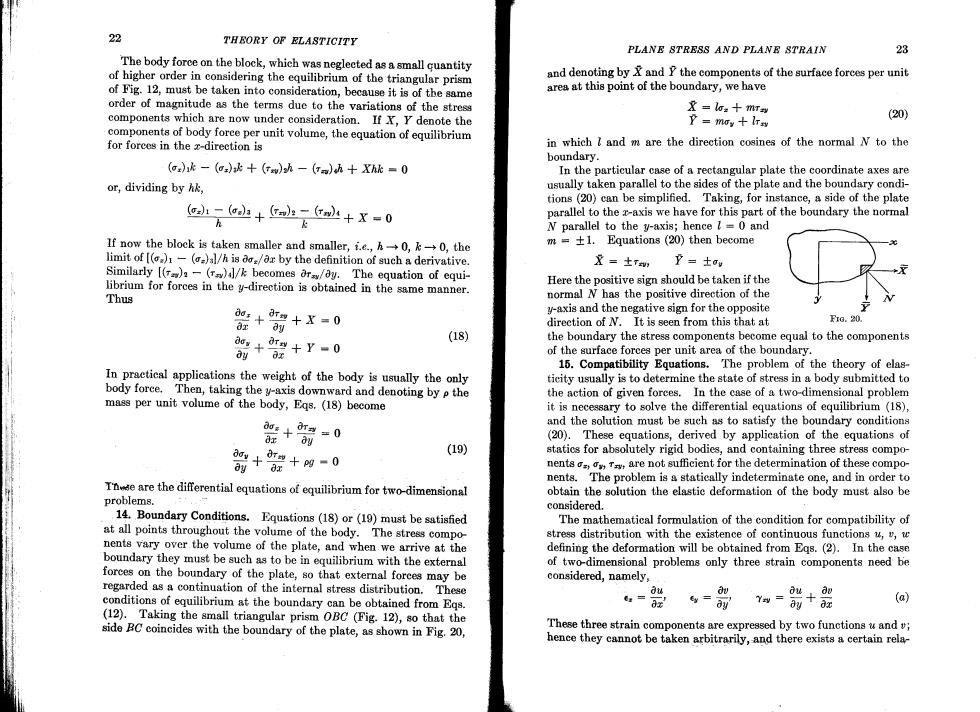
22 THEORY OF ELASTICITY PLANE STRESS AND PLANE STRAIN 23 The body force on the block,which was neglected as a small quantity of higher order in considering the equilibrium of the triangular prism and denoting by and P the components of the surface forces per unit of Fig.12,must be taken into consideration,because it is of the same area at this point of the boundary,we have order of magnitude as the terms duc to the variations of the stress 及=la:+mr到 components which are now under consideration.If X,Y denote the P=moy十rw (20) components of body foree per unit volume,the equation of equilibrium for forces in the x-direction is in which l and m are the direction cosines of the normal N to the boundary. (G)k-(o=)+()h-(T=)h+Xhk=0 In the particular case of a rectangular plate the coordinate axes are or,dividing by hk, usually taken parallel to the sides of the plate and the boundary condi- tions(20)can be simplified.Taking,for instance,a side of the plate -o+-r+X=0 parallel to the z-axis we have for this part of the boundary the normal k N parallel to the y-axis;hence =0 and If now the block is taken smaller and smaller,f.e.,h-0,k-0,the m =+1.Equations (20)then become limit of [()1-(=)al/h is aoz/ax by the definition of such a derivative. 星=±r,卫=士w Similarly [()-()4l/k becomes ara/ay.The equation of equi- librium for forces in the y-direction is obtained in the same manner. Here the positive sign should be taken if the Thus normal N has the positive direction of the 密+时+X=0 y-axis and the negative sign for the opposite direction of N.It is seen from this that at FIo.20. 脂++r-0 (18) the boundary the stress components become equal to the components of the surface forces per unit area of the boundary. 15.Compatibility Equations.The problem of the theory of elas- In practical applications the weight of the body is usually the only ticity usually is to determine the state of stress in a body submitted to body force.Then,taking the y-axis downward and denoting by p the the action of given forces.In the case of a two-dimensional problem mass per unit volume of the body,Egs.(18)become it is necessary to solve the differential equations of equilibrium(18), 密+0 and the solution must be such as to satisfy the boundary conditions (20).These equations,derived by application of the equations of 箭+2+的-0 (19) statics for absolutely rigid bodies,and containing three stress compo- nentsr are not sufficient for the determination of these compo- nents.The problem is a statically indeterminate one,and in order to Tne are the differential equations of equilibrium for two-dimensional obtain the solution the elastic deformation of the body must also be problems. considered. 14.Boundary Conditions.Equations(18)or (19)must be satisfied The mathematical formulation of the condition for compatibility of at all points throughout the volume of the body.The stress compo- stress distribution with the existence of continuous functions u,,w nents vary over the volume of the plate,and when we arrive at the defining the deformation will be obtained from Egs.(2).In the case boundary they must be such as to be in equilibrium with the external of two-dimensional problems only three strain components need be forces on the boundary of the plate,so that external forees may be considered,namely, regarded as a continuation of the internal stress distribution.These d地 conditions of equilibrium at the boundary can be obtained from Eqs. (a) (12).Taking the small triangular prism OBC (Fig.12),so that the side BC coincides with the boundary of the plate,as shown in Fig.20, These three strain components are expressed by two functions u and; hence they cannot be taken arbitrarily,and there exists a certain rela-