
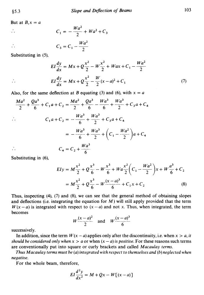
102 Mechanics of Materials §5.3 wx4 wx5 wL3x 23wL4 E1y=-24602+4-120 Then,for example,the deflection at the tip of the cantilever,where x =0,is 23wL4 y=- 120EI 5.3.Macaulay's method The simple integration method used in the previous examples can only be used when a single expression for B.M.applies along the complete length of the beam.In general this is not the case,and the method has to be adapted to cover all loading conditions. Consider,therefore,a small portion of a beam in which,at a particular section A,the shearing force is Q and the B.M.is M,as shown in Fig.5.10.At another section B,distance a along the beam,a concentrated load W is applied which will change the B.M.for points beyond B. Fig.5.10. Between A and B, M=3 =M+Qx () E袋=M+e吃+C (2) and * Ely -M 6+C1x+C2 (3) Beyond B d2y M=EI M+Qx-W(x-a) (4) =Mx+ 22 W2+Wax+C3 (5) ,x2 3 x2 and Ely M 乞+e-+ W6+wa2+Cx+C。 (6) Now for the same slope at B,equating(2)and(5), M+0受+G,=Mr+0写-w x2 x2 2+Wax+C3
102 Mechanics of Materials 55.3 wx4 wx5 wL3x 23wL4 24 6OL 4 120 .. Ely= Then, for example, the deflection at the tip of the cantilever, where x = 0, is 23wL4 y= -___ 120EI 5.3. Macaulay’s method The simple integration method used in the previous examples can only be used when a single expression for B.M. applies along the complete length of the beam. In general this is not the case, and the method has to be adapted to cover all loading conditions. Consider, therefore, a small portion of a beam in which, at a particular section A, the shearing force is Q and the B.M. is M, as shown in Fig. 5.10. At another section B, distance a along the beam, a concentrated load W is applied which will change the B.M. for points beyond B. W 0 IX A B Fig. 5.10. Between A and B, d2Y M = El- dx2 = M +Qx x2 x3 and Ely = M- 2 + Q- 6 + C~X +C2 Beyond B d2Y M = ElT = M+Qx- W(x-a) dx and dY x2 x2 El-=Mx+Q-- W-+ Wax+C3 dx 2 2 x2 x3 x3 X2 2 6 6 Ely= M-+Q-- W-+ Wa-+C3x+C, 2 Now for the same slope at B, equating (2) and (5), X2 x2 x2 2 2 2 Mx+Q-+CC, = Mx+Q-- W-+ Wax+C3
§5.3 Slope and Deflection of Beams 103 But at B,x =a Wa2 C,=-"2+wa2+Cg Wa2 C3=C1- 2 Substituting in (5), Edy-Mx+22- Wa2 dx -W+Wax+C- B张=Mk+e-ar+c: (7) dx Also,for the same deflection at B equating (3)and(6),with x =a ccCC. Ma2 Qa3 C:a+C:-Wat ha +2+C3a+C 2 +(-"加+c Wa3 C4=C2+ 6 Substituting in (6), x2 x3 Wa2\ Ely M 2+ (9-2x+w +C2 2 x3 =M 2+06-w-a 6+C1x+C2 (8) Thus,inspecting (4),(7)and(8),we can see that the general method of obtaining slopes and deflections (i.e.integrating the equation for M)will still apply provided that the term W(x-a)is integrated with respect to (x-a)and not x.Thus,when integrated,the term becomes w(x-a)2 2 and w(x-a) 6 successively. In addition,since the term W(x-a)applies only after the discontinuity,i.e.whenx>a,it should be considered only when x a or when (x-a)is positive.For these reasons such terms are conventionally put into square or curly brackets and called Macaulay terms. Thus Macaulay terms must be (a)integrated with respect to themselves and (b)neglected when negative. For the whole beam,therefore, Ei dx2=M+Qx-W[(x-a)]
$5.3 Slope and Deflection of Beams 103 But at B,x = a .. Wa2 2 c + Wa2 + C3 1- L Substituting in (9, .. dY x2 x2 Wa2 El-=Mx+Q-- W-+ Wax+C,--- dx 2 2 2 dY x2 w El- = Mx + Q- - -(x-a)’ +C, dx 22 Also, for the same deflection at B equating (3) and (6), with x = a Ma2 Qa3 Ma2 Qa3 Wa3 Wa3 -+-+C,a+C, =-+---- + ~ + C3a + C, 2 6 2 6 6 2 .. .. Substituting in (6), Wa3 Wa3 C,a+C2 = -- +- + C3a + C, 6 2 = -__ Wa3+wa3 + ( c,--- y2)a+c, 6 2 Wa c,=c2+- 6 (7) x2 x3 (x - a)3 2 6 6 = M- + Q- - W- + c,x + c, Thus, inspecting (4), (7) and (8), we can see that the general method of obtaining slopes and deflections (i.e. integrating the equation for M) will still apply provided that the term W(x -a) is integrated with respect to (x -a) and not x. Thus, when integrated, the term becomes (x - a)2 W- 2 (x - a)3 and W- 6 successively. In addition, since the term W(x - a) applies only after the discontinuity, i.e. when x > a, it should be considered only when x > a or when (x - a) is positive. For these reasons such terms are conventionally put into square or curly brackets and called Macaulay terms. Thus Macaulay terms must be (a) integrated with respect to themselves and (b) neglected when negative. For the whole beam, therefore, d2Y El, = M+Qx- W[(x-a)] dx

104 Mechanics of Materials §5.3 20kN 30kNIX 。-3m-3m -4m- 2m4 Ra-15 KNI ho kN Fig.5.11. As an illustration of the procedure consider the beam loaded as shown in Fig.5.11 for which the central deflection is required.Using the Macaulay method the equation for the B.M.at any general section XX is then given by B.M.xx=15x-20[(x-3)]+10[(x-6)]-30[(x-10)] Care is then necessary to ensure that the terms inside the square brackets(Macaulay terms) are treated in the special way noted on the previous page. Here it must be emphasised that all loads in the right-hand side of the equation are in units of kN (i.e.newtons x 103).In subsequent working,therefore,it is convenient to carry through this factor as a denominator on the left-hand side in order that the expressions are dimensionally correct. Integrating, =i5-]+0[]-刘[0]+A 103dx r-1s后-刘[。]+0[。]-[。]++a EI and where A and B are two constants of integration. Now when x=0,y=0..B=0 and when x 12,y=0 0-1s2-+[]-刘[+a =4320-2430+360-40+12A 12A=-4680+2470=-2210 A=-184.2 The deflection at any point is given by EI 184.2x The deflection at mid-span is thus found by substituting x=6 in the above equation, bearing in mind that the dimensions of the equation are kNm3. N.B.-Two of the Macaulay terms then vanish since one becomes zero and the other negative and therefore neglected. central deflection= 19[15x6-20X3-1842×6 ET 6 655.2×10³ EI
104 Mechanics of Materials 55.3 Fig. 5.11. As an illustration of the procedure consider the beam loaded as shown in Fig. 5.1 1 for which the central deflection is required. Using the Macaulay method the equation for the B.M. at any general section XX is then given by Care is then necessary to ensure that the terms inside the square brackets (Macaulay terms) are treated in the special way noted on the previous page. Here it must be emphasised that all loads in the right-hand side of the equation are in units of kN (i.e. newtons x lo3). In subsequent working, therefore, it is convenient to carry through this factor as a denominator on the left-hand side in order that the expressions are dimensionally correct. B.M. xx = 15~ - 20[ (X - 3)] + 10[(~ - 6)] - 30[ (X - lo)] Integrating, --=15--20[~]+10[~]-30[( El dy x2 x - 3)2 x - 6)2 x - 10)2 ]+A lo3 dx 2 E1 x3 x - 3)3 x - 6)3 x - 1013 and ~ lo3’= 15- 6 - 20 [ 51 + 10 [ +] - 30[ ( ] + Ax + B where A and B are two constants of integration. Now when x =0, y =O .’. B =O and when x = 12, y = 0 15 x 123 .. o=-- 6 = 4320 - 2430 + 360 - 40 + 12A .. .. A = - 184.2 12A = -4680+2470 = -2210 The deflection at any point is given by E1 x3 x - 3)3 x - 6)3 - 1013 Sy= 6 15- - 20[%] + IO[ $1 - 30[ ( ] - 184.2~ The deflection at mid-span is thus found by substituting x = 6 in the above equation, N.B.-Two of the Macaulay terms then vanish since one becomes zero and the other bearing in mind that the dimensions of the equation are kNm3. negative and therefore neglected. .. central deflection = 655.2 x lo3 E1 - -_
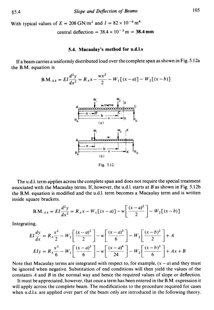
§5.4 Slope and Defection of Beams 105 With typical values of E 208 GN/m2 and I =82 x 10-6 m+ central deflection 38.4 x 10³m 38.4 mm 5.4.Macaulay's method for u.d.l.s If a beam carries a uniformly distributed load over the complete span as shown in Fig.5.12a the B.M.equation is BMr=E1的 Z=RxWx-w1x-四]-[x二b] w/metre 0-B R (a】 (b) Fig.5.12. The u.d.I.term applies across the complete span and does not require the special treatment associated with the Macaulay terms.If,however,the u.d.I.starts at B as shown in Fig.5.12b the B.M.equation is modified and the u.d.1.term becomes a Macaulay term and is written inside square brackets. B.M.Xx =EI -R---[] W2[x-b)] Integrating, 装-号-[]门-[]+A dx =R若-[门[2][]+8 Note that Macaulay terms are integrated with respect to,for example,(x-a)and they must be ignored when negative.Substitution of end conditions will then yield the values of the constants A and B in the normal way and hence the required values of slope or deflection. It must be appreciated,however,that once a term has been entered in the B.M.expression it will apply across the complete beam.The modifications to the procedure required for cases when u.d.l.s.are applied over part of the beam only are introduced in the following theory
45.4 With typical values of E = 208 GN/m2 and I = 82 x Slope and Defection of Beams m4 central deflection = 38.4 x lo-’ m = 38.4 mm 105 5.4. Macaulay’s method for u.d.1.s If a beam carries a uniformly distributed load over the complete span as shown in Fig. 5.12a the B.M. equation is d2Y wx2 B.M.xx= EI-= RAx--- W,[(x-a)]- W2[(x-b)] dx2 2 W W, A A, B Fig. 5.12. The u.d.1. term applies across the complete span and does not require the special treatment associated with the Macaulay terms. If, however, the u.d.1. starts at B as shown in Fig. 5.12b the B.M. equation is modified and the u.d.1. term becomes a Macaulay term and is written inside square brackets. d2Y B.M.xx=El,=RAx-W,[(x-a)]-w dx Integrating, dy x2 EI- = RA- - dx 2 x3 x - a)3 6 Ely = RA- - W, [&-I - w (x -a)’ 6 Note that Macaulay terms are integrated with respect to, for example, (x -a) and they must be ignored when negative. Substitution of end conditions will then yield the values of the constants A and B in the normal way and hence the required values of slope or deflection. It must be appreciated, however, that once a term has been entered in the B.M. expression it will apply across the complete beam. The modifications to the procedure required for cases when u.d.1.s. are applied over part of the beam only are introduced in the following theory

106 Mechanics of Materials §5.5 5.5.Macaulay's method for beams with u.d.I.applied over part of the beam Consider the beam loading case shown in Fig.5.13a. wmetre R (b) Fig.5.13. The B.M.at the section SS is given by the previously introduced procedure as RM.-Rv-w,t Having introduced the last (u.d.l.)term,however,it will apply for all values of x'greater than a,i.e.across the rest of the span to the end of the beam.(Remember,Macaulay terms are only neglected when they are negative,e.g.with x'<a.)The above equation is NOT therefore the correct equation for the load condition shown.The Macaulay method requires that this continuation of the u.d.I.be shown on the loading diagram and the required loading condition can therefore only be achieved by introducing an equal and opposite u.d.l.over the last part of the beam to cancel the unwanted continuation of the initial distributed load.This procedure is shown in Fig.5.13b. The correct B.M.equation for any general section XX is then given by BMa=尝-Rx-x-明-[2]+[] This type of approach can be adopted for any beam loading cases in which u.d.I.s are stopped or added to. A number of examples are shown in Figs.5.14-17.In each case the required loading system is shown first,followed by the continuation and compensating load system and the resulting B.M.equation. 5.6.Macaulay's method for couple applied at a point Consider the beam AB shown in Fig.5.18 with a moment or couple M applied at some point C.Considering the equilibrium of moments about each end in turn produces reactions of M M RA=L upwards, and RB=L downwards These equal and opposite forces then automatically produce the required equilibrium of vertical forces
106 Mechanics of Materials 45.5 5.5. Macaulay's method for beams with u.d.1. applied over part of the beam Consider the beam loading case shown in Fig. 5.13a. X A I Fig. 5.13. The B.M. at the section SS is given by the previously introduced procedure as B.M.ss= RAx'- W,[(x'-a)]- W ['"' - a)2 1 Having introduced the last (u.d.1.) term, however, it will apply for all values of x' greater than a, i.e. across the rest of the span to the end of the beam. (Remember, Macaulay terms are only neglected when they are negative, e.g. with x' < a.) The above equation is NOT therefore the correct equation for the load condition shown. The Macaulay method requires that this continuation of the u.d.1. be shown on the loading diagram and the required loading condition can therefore only be achieved by introducing an equal and opposite u.d.1. over the last part of the beam to cancel the unwanted continuation of the initial distributed load. This procedure is shown in Fig. 5.13b. The correct B.M. equation for any general section XX is then given by d2Y B.M.xx= EZ7 = RAx- W,[(x-a)]-w dx This type of approach can be adopted for any beam loading cases in which u.d.1.s are stopped or added to. A number of examples are shown in Figs. 5.14-17. In each case the required loading system is shown first, followed by the continuation and compensating load system and the resulting B.M. equation. 5.6. Macaulay's method for couple applied at a point Consider the beam AB shown in Fig. 5.18 with a moment or couple M applied at some point C. Considering the equilibrium of moments about each end in turn produces reactions of M RA=x upwards, and RB=L downwards M These equal and opposite forces then automatically produce the required equilibrium of vertical forces