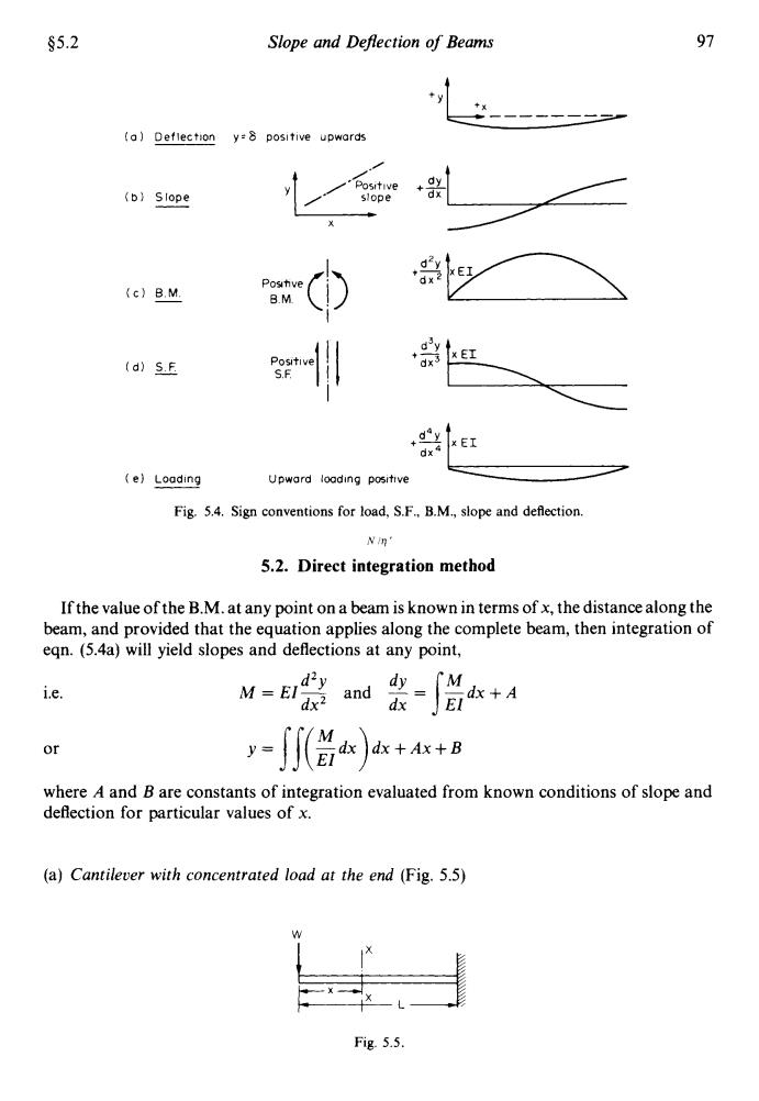
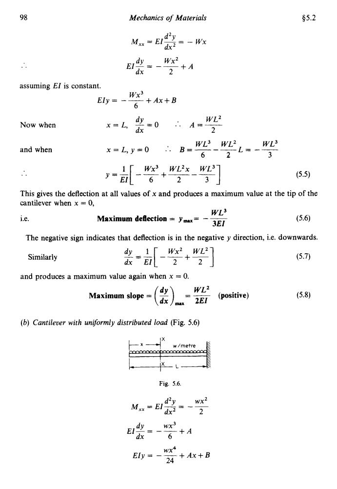
§5.2 Slope and Deflection of Beams 97 (a)Deflection y=8 positive upwards Positive dy (b)Slope slope d d" Postve dx (c)B.M. B.M (d)S.F (e)Loading Upward loading positive Fig.5.4.Sign conventions for load,S.F..B.M.,slope and deflection. N in' 5.2.Direct integration method If the value of the B.M.at any point on a beam is known in terms of x,the distance along the beam,and provided that the equation applies along the complete beam,then integration of eqn.(5.4a)will yield slopes and deflections at any point, ie. dx+A or y=∬(0x++8 where A and B are constants of integration evaluated from known conditions of slope and deflection for particular values of x. (a)Cantilever with concentrated load at the end (Fig.5.5) Fig.5.5
45.2 Slope and Deflection of Beams 97 (a) Deflection y=8 positive upwards (e) Loading Upward loading positive +a .,:.i XEI , Fig. 5.4. Sign conventions for load, S.F., B.M., slope and deflection. Nlq' 5.2. Direct integration method If the value ofthe B.M. at any point on a beam is known in terms of x, the distance along the beam, and provided that the equation applies along the complete beam, then integration of eqn. (5.4a) will yield slopes and deflections at any point, i.e. or dxy s" El y = Is( Zdx) dx +Ax + B d2Y M = EI, and -= --dx+A dx where A and B are constants of integration evaluated from known conditions of slope and deflection for particular values of x. (a) Cantilever with concentrated load at the end (Fig. 5.5) w Fig. 5.5
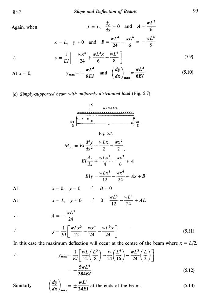
98 Mechanics of Materials $5.2 Mx=E d2y dx2=-Wx EI dy Wx2 =-2+A dx assuming El is constant. E=、 W 6+A+B Now when x=bk y=0.A=) and when x=L,y=0.B= WL3 WL2.WL3 6- -L= 2 3 Wx3 WL2x WL3 E-6+2-3 (5.5) This gives the deflection at all values of x and produces a maximum value at the tip of the cantilever when x =0, WL3 i.e. Maximum deflection ymax=- (5.6) 3EI The negative sign indicates that deflection is in the negative y direction,i.e.downwards. Wx2 WL2 Similarly (5.7) and produces a maximum value again when x=0. dy WL2 Maximum slope (5.8) dx 2EI (positive) max (b)Cantilever with uniformly distributed load (Fig.5.6) w/metre Fig.5.6. Mxx=EI d2y wx2 2 2 Eldy wx3 dx 6+A Ely =wxt 24 +Ax+B
98 Mechanics of Materials $5.2 .. d2Y M,, = EIy = - WX dx dy Wx2 dx 2 EI-= --+A assuming EI is constant. wx3 EIy= --+Ax+B 6 Now when x=L, -- dy - 0 :. dx w12 2 A=---- and when .. WL3 WLZ w13 6 2 3 x=L,y=Q .’. B=---L= -- --+--- EI 6 2 (5.5) This gives the deflection at all values of x and produces a maximum value at the tip of the cantilever when x = 0, i.e. w13 Maximum deflection = y,= - - 3e1 The negative sign indicates that deflection is in the negative y direction, i.e. downwards. Similarly dY 1 wx2 WL2 dx EI and produces a maximum value again when x = 0. Maximum slope = (2) , =- w12 (positive) 2EI (b) Cantilever with uniformly distributed load (Fig. 5.6) Fig. 5.6. d2y wx2 dx2 2 M =EI-=---- xx dy wx3 dx 6 wx4 EIy= --+Ax+B 24 EI-= --+A (5.7)
s5.2 Slope and Deflection of Beams 99 Again,when =0andA=wL x=L dx x=L y=0 and B=wL4wLi wL4 24 6、 8 y= wx4 wL3x wL4 24+ (5.9) EI 68 wL4 dy wL3 Atx=0, and (5.10) 8EI dx m 6EI (c)Simply-supported beam with uniformly distributed load(Fig.5.7) w/metre xbecccoxceecc wL Fig.5.7. M=E1=wLx、w dr= 2 2 El dywLx2 wx dx 4 6+A Ely =WLx3 wxt 1224+Ax+B At x=0,y=0 ∴.B=0 At x=L,y=0 0=WL4 wL4 1224+AL A=、wL3 24 1「wLx3wx4wL3x7 y=El12-24-24 (5.11) In this case the maximum deflection will occur at the centre of the beam where x=L/2. ()-()()】 5wL+ (5.12) 384EI Similarly dy WL3 dx 4E at the ends of the beam. (5.13)
$5.2 Again, when Slope and Deflection of Beams dY w13 x=L, -=0 and A=- dx 6 .. At x = 0, wL4 w13 y,= -__ and (2) =- 8El rmx 6El (c) Simply-supported beam with uniformly distributed load (Fig. 5.7) I' w/metre - WL - WL 2 2 Fig. 5.1. d2y wLx wx2 dx2 2 2. M =El-=--- xx dy wLx2 wx3 dx 4 6 wLx3 wx4 12 24 EI- = __ +A - ~ Ely = ~ - __ +Ax+B At x=O, y=O .'. B=O At 99 (5.9) (5.10) (5.11) In this case the maximum deflection will occur at the centre of the beam where x = L/2. .. - 5wL4 - -__ 384El WL3 , 24EI Similarly (2) =*- at the ends of the beam. (5.12) (5.13)

100 Mechanics of Materials §5.2 (d)Simply supported beam with central concentrated load (Fig.5.8) Fig.5.8. In order to obtain a single expression for B.M.which will apply across the complete beam in this case it is convenient to take the origin for x at the centre,then: =最-作--以坠 E少=WL、Wx2 4+A Ely -WLx2 Wx 812+Ax+B At y=0.A=0 +=⊙、x L x=2y=0 ∴.0= WL3 WL3 3296 +B WL3 B=- 48 (5.14) WL3 ymax= at the centre 48EI (5.15) and WL2 at the ends (5.16) /max =士16E1 In some cases it is not convenient to commence the integration procedure with the B.M. equation since this may be difficult to obtain.In such cases it is often more convenient to commence with the equation for the loading at the general point XX on the beam.A typical example follows:
100 Mechanics of Materials $5.2 (d) Simply supported beam with central concentrated load (Fig. 5.8) W Fig. 5.8. In order to obtain a single expression for B.M. which will apply across the complete beam in this case it is convenient to take the origin for x at the centre, then: WLX2 wx3 8 12 Ely = ~-__ +Ax+B At dY x=o, -=o :. dx L 2’ x=- y=o WL3 WL3 O=- -__ +B 32 96 (5.14) 12 48 Y=- = -___ .. wL3 at the centre ymax 48EI and at the ends WLZ (5.15) (5.16) In some cases it is not convenient to commence the integration procedure with the B.M. equation since this may be difficult to obtain. In such cases it is often more convenient to commence with the equation for the loading at the general point XX on the beam. A typical example follows:
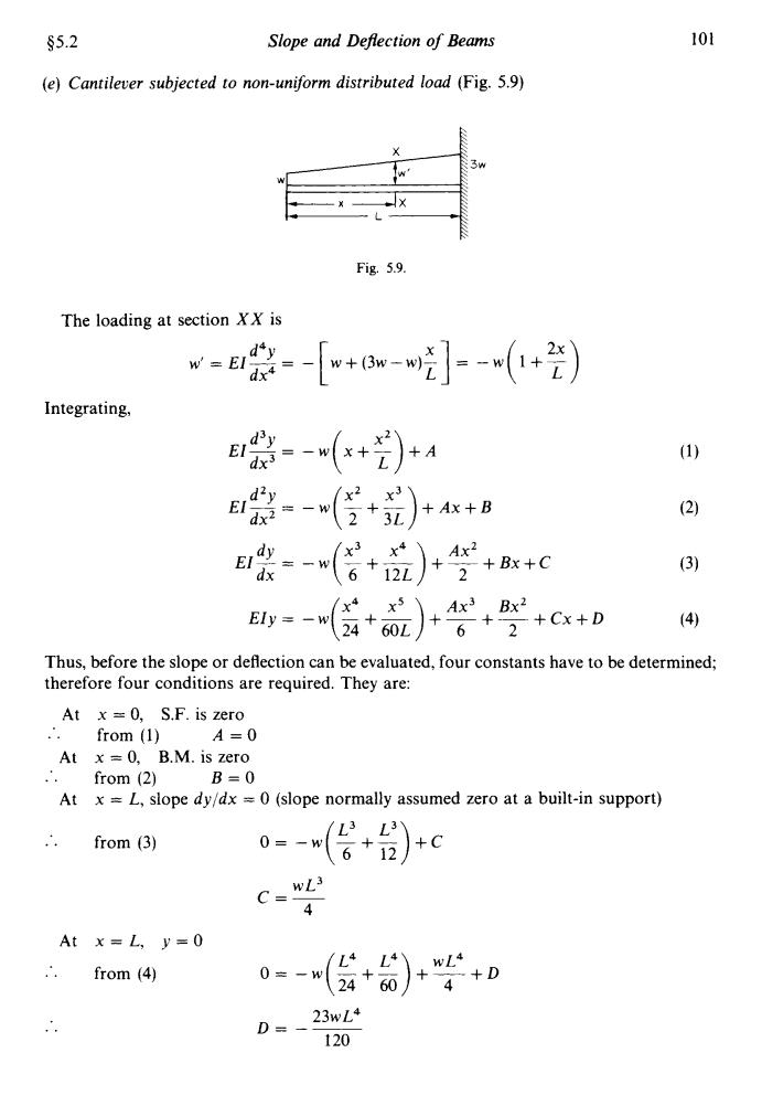
§5.2 Slope and Deflection of Beams 101 (e)Cantilever subjected to non-uniform distributed load (Fig.5.9) + w 3w Fig.5.9. The loading at section XX is -票-+6w-引-(+) Integrating, 装-(+)+A (1) Erdzy=wt3 (2+3+Ax+B (2) -(+品 /x3,x4 Ax +Bx+C 3 /x4 E1y=-w24+ Ax3 Bx2 + 60L 6* 2+Cx+D (4) Thus,before the slope or deflection can be evaluated,four constants have to be determined; therefore four conditions are required.They are: At x=0,S.F.is zero .from (1)A=0 At x =0,B.M.is zero from (2) B=0 At x =L,slope dy/dx =0(slope normally assumed zero at a built-in support) from (3) 0=-w +) 6 +C C= 4 At x=L,y=0 /L4 from (4) 0=-w ,L4 WL4 24 60 +4+D D=、 23wL4 120
$5.2 Slope and DeJIection of Beams 101 (e) Cantilever subjected to non-uniform distributed load (Fig. 5.9) Fig. 5.9. The loading at section XX is w‘ = El- d4Y = - [ w + (3w - w)’] = - w (1 + %) dx4 1 Integrating, E~-=-w d2y (; -+- ;I) +A x+B dx2 (;: 6.6,) Ax3 Bx2 (4) Ely= -W -+- +-+--++x+D 62 (3) Thus, before the slope or deflection can be evaluated, four constants have to be determined; therefore four conditions are required. They are: At x = 0, S.F. is zero .‘. from (1) A=O At x = 0, B.M. is zero .’. from (2) B=O At x = L, slope dyldx = 0 (slope normally assumed zero at a built-in support) .’. from (3) At x=L, y=O ... from (4) o=-w -+- +C (: ti) O= -w($+$)+F+D .. 23wL4 120 D= -~