AΛA d sine/A Figure 14.3.2 Intensity as a function of dsin/ For small angle 0,using Eq.(14.2.7),the intensity can be rewritten as I=1o cos πd (14.2.24) Example 14.2:Intensity of Three-Slit Interference Suppose a monochromatic coherent source of light passes through three parallel slits, each separated by a distance d from its neighbor,as shown in Figure 14.3.3. S Figure 14.3.3 Three-slit interference. The waves have the same amplitude Eo and angular frequency @but a constant phase differenceφ=2πdsin0/λ. (a)Show that the intensity is -+2a0j (14.2.25) 14-11
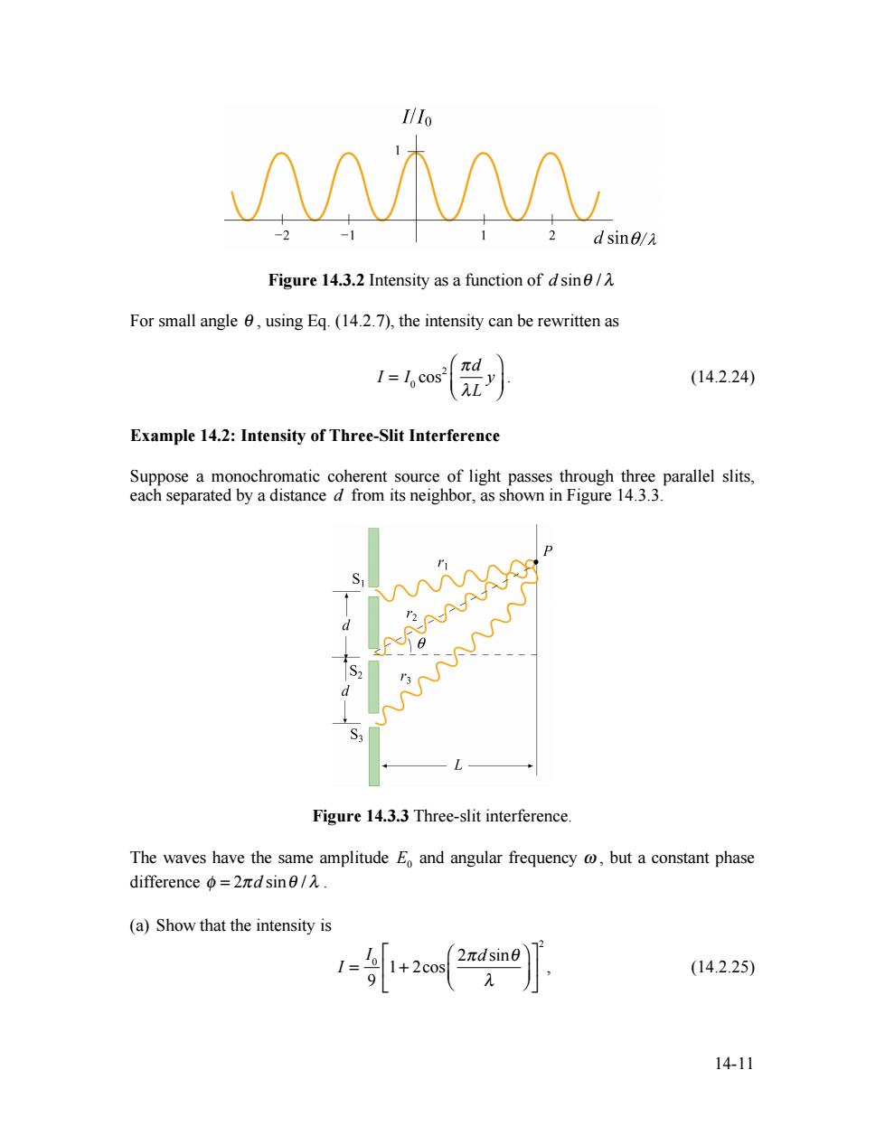
14-11 Figure 14.3.2 Intensity as a function of d sinθ / λ For small angle θ , using Eq. (14.2.7), the intensity can be rewritten as I = I0 cos2 πd λL y ⎛ ⎝ ⎜ ⎞ ⎠ ⎟ . (14.2.24) Example 14.2: Intensity of Three-Slit Interference Suppose a monochromatic coherent source of light passes through three parallel slits, each separated by a distance d from its neighbor, as shown in Figure 14.3.3. Figure 14.3.3 Three-slit interference. The waves have the same amplitude E0 and angular frequency ω , but a constant phase difference φ = 2π d sinθ / λ . (a) Show that the intensity is I = I0 9 1+ 2cos 2πd sinθ λ ⎛ ⎝ ⎜ ⎞ ⎠ ⎟ ⎡ ⎣ ⎢ ⎤ ⎦ ⎥ 2 , (14.2.25)

where 1o is the maximum intensity associated with the primary maxima (b)What is the ratio of the intensities of the primary and secondary maxima? Solutions: (a)Let the three waves emerging from the slits be described by the functions E=E sin(@t),E,=E sin(at+),E=E sin(@t+20). (14.2.26) Using the trigonometric identity sin+sinB=2cos 2 (14.2.27) the sum of E and E3 is E +E=E sin(ct)+sin(ot+2)=2E cos()sin(@t+). (14.2.28) The total electric field at the point P on the screen is then the sum E=E,+E3+E2=E。sin(or+φ)2cos(p)+1). (14.2.29) The intensity is proportional to 1c(E)=E,22cos()+1(sin2(o+》=E,2(2cos(o)+12,142.30) where we have used (sin2(+)=1/2.The maximum intensity is attained when coso=1.Thus, 1(1+2cos() (14.2.31) 9 SubstituteΦ=2πdsinθ/2 into Eq.(l4.2.3l).Then the intensity is 1-0+2o-号+2o20 2nd sine (14.2.32) (b)The interference pattern is shown in Figure 14.3.4. 14-12
14-12 where 0 I is the maximum intensity associated with the primary maxima. (b) What is the ratio of the intensities of the primary and secondary maxima? Solutions: (a) Let the three waves emerging from the slits be described by the functions E1 = E0 sin(ωt), E2 = E0 sin(ωt + φ), E3 = E0 sin(ωt + 2φ) . (14.2.26) Using the trigonometric identity sinα + sinβ = 2cos α − β 2 ⎛ ⎝ ⎜ ⎞ ⎠ ⎟ sin α + β 2 ⎛ ⎝ ⎜ ⎞ ⎠ ⎟ , (14.2.27) the sum of E1 and E3 is E1 + E3 = E0 ⎡sin(ωt) + sin(ωt + 2φ) ⎣ ⎤ ⎦ = 2E0 cos(φ)sin(ωt + φ) . (14.2.28) The total electric field at the point P on the screen is then the sum E = E1 + E3 + E2 = E0 sin(ωt + φ)(2cos(φ) + 1). (14.2.29) The intensity is proportional to 2 E , I ∝ E2 = E0 2 (2cos(φ) + 1) 2 sin2 (ωt + φ) = 1 2 E0 2 (2cos(φ) + 1) 2 , (14.2.30) where we have used sin2 (ωt + φ) = 1/ 2 . The maximum intensity 0 I is attained when cosφ =1. Thus, I I0 = (1+ 2cos(φ)) 2 9 . (14.2.31) Substitute φ = 2π d sinθ / λ into Eq. (14.2.31). Then the intensity is ( ) 2 2 0 0 2 sin 1 2cos 1 2cos 9 9 I I d I π θ φ λ ⎡ ⎛ ⎞⎤ = + = ⎢ + ⎜ ⎟⎥ ⎣ ⎝ ⎠⎦ . (14.2.32) (b) The interference pattern is shown in Figure 14.3.4

IlIo primary maximum 0.8 0.6 0.4 secondary maximum 0.2 dsine/A -1.5-1 -0.5 0.5 1 1.5 Figure 14.3.4 Intensity pattern for triple slit interference. From the figure,we see that the minimum intensity is zero,and occurs when coso=-1/2.The condition for primary maxima is coso=+1,which gives 1/1o=1.In addition,there are also secondary maxima that are located at cos=-1.The condition implies o=(2m+1)r,which implies that dsin0/2=(m+l/2),m=0,±l,±2,…,The intensity ratio is I/1=1/9 14.4 Diffraction In addition to interference,waves also exhibit another property-diffraction,which is the bending of waves as they pass by some objects or through an aperture.The phenomenon of diffraction can be understood using the Huygens-Fresnel principle that states that Every unobstructed point on a wavefront will act a source of secondary spherical waves. The new wavefront is the surface tangent to all the secondary spherical waves. Figure 14.4.1 illustrates the propagation of the wave based on the Huygens-Fresnel principle. c△t Figure 14.4.1 Huygens-Fresnel principle According to the Huygens-Fresnel principle,light waves incident on two slits will spread out and exhibit an interference pattern in the region beyond(Figure 14.4.2a).The pattern is called a diffraction pattern.On the other hand,if no bending occurs and the light wave 14-13
14-13 Figure 14.3.4 Intensity pattern for triple slit interference. From the figure, we see that the minimum intensity is zero, and occurs when cosφ = −1/ 2. The condition for primary maxima is cosφ = +1, which gives 0 I / I =1. In addition, there are also secondary maxima that are located at cosφ = −1. The condition implies φ = (2m + 1)π , which implies that d sinθ / λ = (m + 1 / 2), m = 0,± 1,± 2,. The intensity ratio is 0 I / I =1/ 9. 14.4 Diffraction In addition to interference, waves also exhibit another property – diffraction, which is the bending of waves as they pass by some objects or through an aperture. The phenomenon of diffraction can be understood using the Huygens-Fresnel principle that states that Every unobstructed point on a wavefront will act a source of secondary spherical waves. The new wavefront is the surface tangent to all the secondary spherical waves. Figure 14.4.1 illustrates the propagation of the wave based on the Huygens-Fresnel principle. Figure 14.4.1 Huygens-Fresnel principle. According to the Huygens-Fresnel principle, light waves incident on two slits will spread out and exhibit an interference pattern in the region beyond (Figure 14.4.2a). The pattern is called a diffraction pattern. On the other hand, if no bending occurs and the light wave