Chapter 14 Interference and Diffraction 14.1 Superposition of Waves....................... 14-2 14.1.1 Interference Conditions for Light Sources.... 14-4 14.2 Young's Double-Slit Experiment..... 14-4 Example 14.1:Double-Slit Experiment................ 14-8 14.3 Intensity Distribution 14-8 Example 14.2:Intensity of Three-Slit Interference... 14-11 14.4 Diffraction............. 14-13 14.5 Single-Slit Diffraction.................. 14-14 Example 14.3:Single-Slit Diffraction............ 14-16 14.6 Intensity of Single-Slit Diffraction..... 14-17 14.7 Intensity of Double-Slit Diffraction Patterns. 14-21 14.8 Diffraction Grating.. 14-22 14.9 Summary.… 14-23 14.10 Appendix:Computing the Total Electric Field... 14-24 14.11 Solved Problems ............... 14-28 14.11.1 Double-Slit Experiment.................... 14-28 14.11.2 Phase Difference................ 14-29 14.11.3 Constructive Interference................ 14-30 14.11.4 Intensity in Double-Slit Interference 14-31 14.11.5 Second-Order Bright Fringe........ 14-32 14.11.6 Intensity in Double-Slit Diffraction.. 14-32 14.12 Conceptual Questions................. 14-35 14.13 Additional Problems..... 14-35 14.13.1 Double-Slit Interference..... .14-35 14.13.2 Interference-Diffraction Pattern.. 14-36 14.13.3 Three-Slit Interference..... 14-36 14.13.4 Intensity of Double-Slit Interference........................... 14-36 14.13.5 Secondary Maxima............ 14-36 14.13.6 Interference-Diffraction Pattern. 14-37 14-1
14-1 Chapter 14 Interference and Diffraction 14.1 Superposition of Waves................................................................................... 14-2 14.1.1 Interference Conditions for Light Sources............................................... 14-4 14.2 Young’s Double-Slit Experiment .................................................................... 14-4 Example 14.1: Double-Slit Experiment................................................................. 14-8 14.3 Intensity Distribution ....................................................................................... 14-8 Example 14.2: Intensity of Three-Slit Interference ............................................. 14-11 14.4 Diffraction...................................................................................................... 14-13 14.5 Single-Slit Diffraction.................................................................................... 14-14 Example 14.3: Single-Slit Diffraction ................................................................. 14-16 14.6 Intensity of Single-Slit Diffraction ................................................................ 14-17 14.7 Intensity of Double-Slit Diffraction Patterns................................................. 14-21 14.8 Diffraction Grating......................................................................................... 14-22 14.9 Summary........................................................................................................ 14-23 14.10 Appendix: Computing the Total Electric Field.............................................. 14-24 14.11 Solved Problems ............................................................................................ 14-28 14.11.1 Double-Slit Experiment ....................................................................... 14-28 14.11.2 Phase Difference .................................................................................. 14-29 14.11.3 Constructive Interference..................................................................... 14-30 14.11.4 Intensity in Double-Slit Interference ................................................... 14-31 14.11.5 Second-Order Bright Fringe ................................................................ 14-32 14.11.6 Intensity in Double-Slit Diffraction..................................................... 14-32 14.12 Conceptual Questions .................................................................................... 14-35 14.13 Additional Problems ...................................................................................... 14-35 14.13.1 Double-Slit Interference....................................................................... 14-35 14.13.2 Interference-Diffraction Pattern........................................................... 14-36 14.13.3 Three-Slit Interference ......................................................................... 14-36 14.13.4 Intensity of Double-Slit Interference ................................................... 14-36 14.13.5 Secondary Maxima .............................................................................. 14-36 14.13.6 Interference-Diffraction Pattern........................................................... 14-37

Interference and Diffraction 14.1 Superposition of Waves Consider a region in space where two or more waves pass through at the same time. According to the superposition principle,the net displacement is simply given by the vector or the algebraic sum of the individual displacements.Interference is the combination of two or more waves to form a composite wave,based on such principle. The idea of the superposition principle is illustrated in Figure 14.1.1. constructive interference b) Figure 14.1.1 Superposition of waves.(a)Traveling wave pulses approach each other, (b)constructive interference,(c)destructive interference,(d)waves move apart. Suppose we are given two waves, y(x,t)=Ψ。sin(kx±0t+9) Ψ2(x,1)=Ψ20sin(kx±0,1+,).(14.1.1) The resulting sum of the two waves is y(x,)=Ψosin(kx±ω,t+9)+Ψ2osin(k3x±ω,1+92) (14.1.2) The interference is constructive if the amplitude of y(x,t)is greater than the individual ones(Figure 14.1.1b),and destructive if smaller (Figure 14.1.1c). As an example,consider the superposition of the following two waves at t=0: y,(x)=sinx,Ψ,(x)=2sin(x+π/4) (14.1.3) The resultant wave is given by 14-2
14-2 Interference and Diffraction 14.1 Superposition of Waves Consider a region in space where two or more waves pass through at the same time. According to the superposition principle, the net displacement is simply given by the vector or the algebraic sum of the individual displacements. Interference is the combination of two or more waves to form a composite wave, based on such principle. The idea of the superposition principle is illustrated in Figure 14.1.1. (a) (b) (c) (d) Figure 14.1.1 Superposition of waves. (a) Traveling wave pulses approach each other, (b) constructive interference, (c) destructive interference, (d) waves move apart. Suppose we are given two waves, ψ 1 (x,t) = ψ 10 sin(k1 x ± ω1 t + φ1 ), ψ 2 (x,t) = ψ 20 sin(k2 x ±ω2 t + φ2 ). (14.1.1) The resulting sum of the two waves is ψ (x,t) = ψ10 sin(k1 x ±ω1 t + φ1) +ψ 20 sin(k2 x ±ω2 t + φ2 ). (14.1.2) The interference is constructive if the amplitude of ψ (x,t) is greater than the individual ones (Figure 14.1.1b), and destructive if smaller (Figure 14.1.1c). As an example, consider the superposition of the following two waves at t = 0 : ψ1(x) = sin x, ψ 2 (x) = 2sin(x + π / 4) (14.1.3) The resultant wave is given by
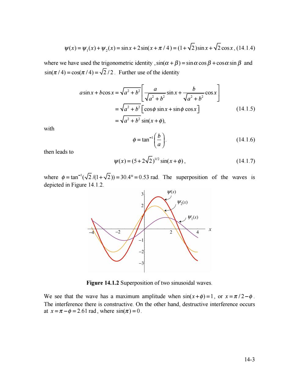
W(x)=W(x)+w,(x)=sinx+2sin(x+/4)=(1+2)sinx+2cosx,(14.1.4) where we have used the trigonometric identity,sin(a+B)=sina cos B+cosa sin B and sin(/4)=cos(/4)=2/2.Further use of the identity asinx+bcosx=a2+b2 _sinx+ √a+ =a2+b2[coso sinx+sino cosx (14.1.5) =√a2+b2sin(x+p), with =tan a (14.1.6) then leads to w(x)=(5+2v2)"sin(x+0), (14.1.7) where =tan-(+))=30.4=0.53 rad.The superposition of the waves is depicted in Figure 14.1.2. 3 W(x) 2(x) ) -2 Figure 14.1.2 Superposition of two sinusoidal waves. We see that the wave has a maximum amplitude when sin(x+)=1,or x=/2-6. The interference there is constructive.On the other hand,destructive interference occurs atx=π-Φ=2.6lrad,where sin(π)=0. 14-3
14-3 ψ(x) = ψ1(x) +ψ 2 (x) = sin x + 2sin(x + π / 4) = (1+ 2)sin x + 2 cos x , (14.1.4) where we have used the trigonometric identity ,sin(α + β ) = sinα cos β + cosα sin β and sin(π / 4) = cos(π / 4) = 2 / 2 . Further use of the identity asin x + bcos x = a 2 + b2 a a 2 + b2 sin x + b a 2 + b2 cos x ⎡ ⎣ ⎢ ⎤ ⎦ ⎥ = a 2 + b2 ⎡cosφ sin x + sinφ cos x ⎣ ⎤ ⎦ = a 2 + b2 sin(x + φ), (14.1.5) with 1 tan b a φ − ⎛ ⎞ = ⎜ ⎟ ⎝ ⎠ . (14.1.6) then leads to ψ(x) = (5 + 2 2) 1/ 2 sin(x + φ) , (14.1.7) where 1 φ tan ( 2 /(1 2)) 30.4 0.53 rad. − = + = ° = The superposition of the waves is depicted in Figure 14.1.2. Figure 14.1.2 Superposition of two sinusoidal waves. We see that the wave has a maximum amplitude when sin(x +φ) =1, or x = π / 2 −φ . The interference there is constructive. On the other hand, destructive interference occurs at x = π −φ = 2.61 rad , where sin(π ) = 0
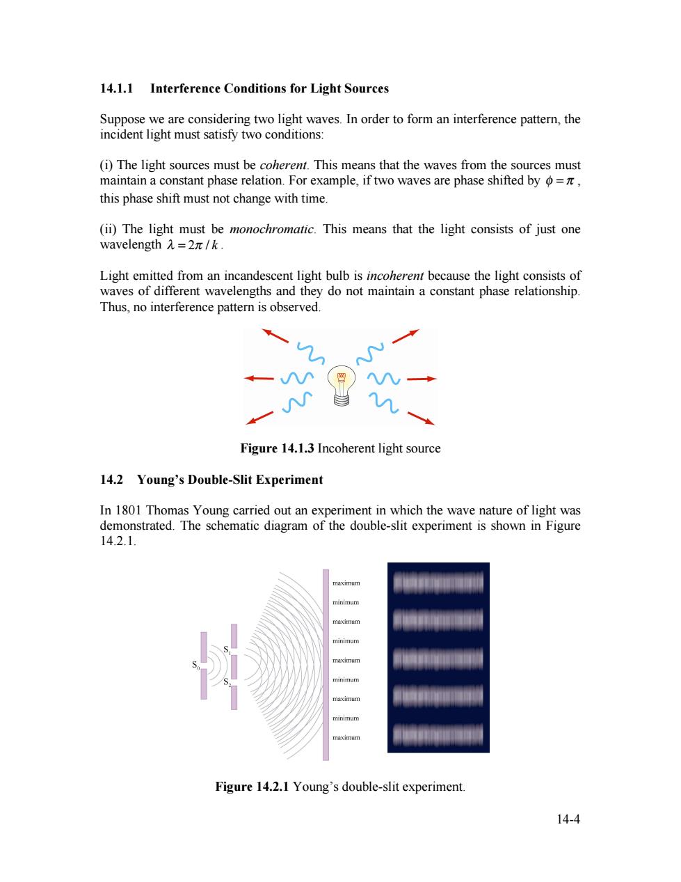
14.1.1 Interference Conditions for Light Sources Suppose we are considering two light waves.In order to form an interference pattern,the incident light must satisfy two conditions: (i)The light sources must be coherent.This means that the waves from the sources must maintain a constant phase relation.For example,if two waves are phase shifted by o=, this phase shift must not change with time. (ii)The light must be monochromatic.This means that the light consists of just one wavelengthλ=2π/k. Light emitted from an incandescent light bulb is incoherent because the light consists of waves of different wavelengths and they do not maintain a constant phase relationship. Thus,no interference pattern is observed. Figure 14.1.3 Incoherent light source 14.2 Young's Double-Slit Experiment In 1801 Thomas Young carried out an experiment in which the wave nature of light was demonstrated.The schematic diagram of the double-slit experiment is shown in Figure 14.2.1. naximum minimum maximum maximum Figure 14.2.1 Young's double-slit experiment. 14-4
14-4 14.1.1 Interference Conditions for Light Sources Suppose we are considering two light waves. In order to form an interference pattern, the incident light must satisfy two conditions: (i) The light sources must be coherent. This means that the waves from the sources must maintain a constant phase relation. For example, if two waves are phase shifted by φ = π , this phase shift must not change with time. (ii) The light must be monochromatic. This means that the light consists of just one wavelength λ = 2π / k . Light emitted from an incandescent light bulb is incoherent because the light consists of waves of different wavelengths and they do not maintain a constant phase relationship. Thus, no interference pattern is observed. Figure 14.1.3 Incoherent light source 14.2 Young’s Double-Slit Experiment In 1801 Thomas Young carried out an experiment in which the wave nature of light was demonstrated. The schematic diagram of the double-slit experiment is shown in Figure 14.2.1. Figure 14.2.1 Young’s double-slit experiment
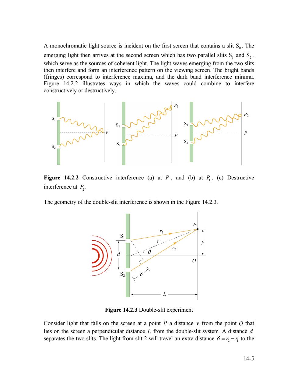
A monochromatic light source is incident on the first screen that contains a slit So.The emerging light then arrives at the second screen which has two parallel slits S,and S,. which serve as the sources of coherent light.The light waves emerging from the two slits then interfere and form an interference pattern on the viewing screen.The bright bands (fringes)correspond to interference maxima,and the dark band interference minima. Figure 14.2.2 illustrates ways in which the waves could combine to interfere constructively or destructively. P Figure 14.2.2 Constructive interference (a)at P,and (b)at P.(c)Destructive interference at B. The geometry of the double-slit interference is shown in the Figure 14.2.3. S Figure 14.2.3 Double-slit experiment Consider light that falls on the screen at a point P a distance y from the point O that lies on the screen a perpendicular distance L from the double-slit system.A distance d separates the two slits.The light from slit 2 will travel an extra distance =,-n to the 14-5
14-5 A monochromatic light source is incident on the first screen that contains a slit S0 . The emerging light then arrives at the second screen which has two parallel slits S1 and S2 . which serve as the sources of coherent light. The light waves emerging from the two slits then interfere and form an interference pattern on the viewing screen. The bright bands (fringes) correspond to interference maxima, and the dark band interference minima. Figure 14.2.2 illustrates ways in which the waves could combine to interfere constructively or destructively. Figure 14.2.2 Constructive interference (a) at P , and (b) at P1 . (c) Destructive interference at P2 . The geometry of the double-slit interference is shown in the Figure 14.2.3. Figure 14.2.3 Double-slit experiment Consider light that falls on the screen at a point P a distance y from the point O that lies on the screen a perpendicular distance L from the double-slit system. A distance d separates the two slits. The light from slit 2 will travel an extra distance 2 1 δ = r − r to the