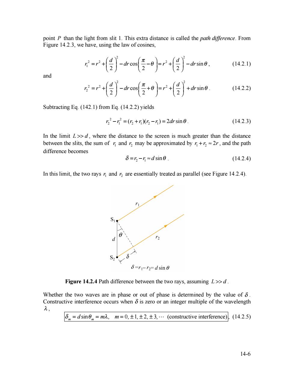
point P than the light from slit 1.This extra distance is called the path difference.From Figure 14.2.3,we have,using the law of cosines, =r侣j-a任-+m. (14.2.1) and =r+-m任+r+侵 (14.2.2) Subtracting Eq.(142.1)from Eq.(14.2.2)yields 52-r2=(5+r)5-r)=2 drsin6. (14.2.3) In the limit L>>d,where the distance to the screen is much greater than the distance between the slits,the sum of n and r may be approximated by r+r=2r,and the path difference becomes δ=5-片=dsin6. (14.2.4) In this limit,the two rays ni and r are essentially treated as parallel (see Figure 14.2.4). S1 d '2 S2 8=r-r2=dsine Figure 14.2.4 Path difference between the two rays,assuming L>>d. Whether the two waves are in phase or out of phase is determined by the value of 8. Constructive interference occurs when is zero or an integer multiple of the wavelength 2, δn=dsin9n=m2,m=O,±l,±2,±3,.(constructive interference) (14.2.5) 14-6
14-6 point P than the light from slit 1. This extra distance is called the path difference. From Figure 14.2.3, we have, using the law of cosines, 2 2 2 2 2 1 cos sin 2 2 2 d d r r dr r dr π θ θ ⎛ ⎞ ⎛ ⎞ ⎛ ⎞ = + ⎜ ⎟ − ⎜ − ⎟ = + ⎜ ⎟ − ⎝ ⎠ ⎝ ⎠ ⎝ ⎠ , (14.2.1) and 2 2 2 2 2 2 cos sin 2 2 2 d d r r dr r dr π θ θ ⎛ ⎞ ⎛ ⎞ ⎛ ⎞ = + ⎜ ⎟ − ⎜ + ⎟ = + ⎜ ⎟ + ⎝ ⎠ ⎝ ⎠ ⎝ ⎠ . (14.2.2) Subtracting Eq. (142.1) from Eq. (14.2.2) yields 2 2 2 1 2 1 2 1 r − r = (r + r )(r − r ) = 2drsinθ . (14.2.3) In the limit L >> d , where the distance to the screen is much greater than the distance between the slits, the sum of 1 r and 2r may be approximated by 1 2 r + r ≈ 2r, and the path difference becomes 2 1 δ = r − r ≈ d sinθ . (14.2.4) In this limit, the two rays 1 r and 2r are essentially treated as parallel (see Figure 14.2.4). Figure 14.2.4 Path difference between the two rays, assuming L >> d . Whether the two waves are in phase or out of phase is determined by the value of δ . Constructive interference occurs when δ is zero or an integer multiple of the wavelength λ , δ m = d sinθ m = mλ, m = 0, ± 1, ± 2, ± 3, (constructive interference) , (14.2.5)
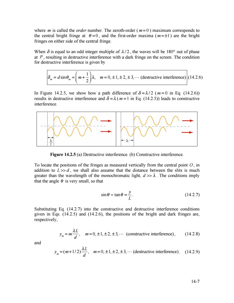
where m is called the order number.The zeroth-order (m=0)maximum corresponds to the central bright fringe at 0=0,and the first-order maxima (m=+1)are the bright fringes on either side of the central fringe. When 6 is equal to an odd integer multiple of A/2,the waves will be 180 out of phase at P,resulting in destructive interference with a dark fringe on the screen.The condition for destructive interference is given by δnm=dsin6n= m+2 2,m=0,±l,±2,±3,…(destructive interference) (14.2.6) In Figure 14.2.5,we show how a path difference of =/2 (m=0 in Eq.(14.2.6)) results in destructive interference and 6=(m=1 in Eq.(14.2.5))leads to constructive interference. XX二 Figure 14.2.5(a)Destructive interference.(b)Constructive interference To locate the positions of the fringes as measured vertically from the central point O,in addition to L>>d,we shall also assume that the distance between the slits is much greater than the wavelength of the monochromatic light,d>>.The conditions imply that the angle 0 is very small,so that sin=tan= (14.2.7) Substituting Eq.(14.2.7)into the constructive and destructive interference conditions given in Eqs.(14.2.5)and (14.2.6),the positions of the bright and dark fringes are, respectively, L y =m- a,m=0,±l,±2,±3…(oructiveinrrence)), (14.2.8) and =(m+1/2)2 ,m=0,±l,±2,±3,(destructiveintre).(l429y 14-7
14-7 where m is called the order number. The zeroth-order ( m = 0 ) maximum corresponds to the central bright fringe at θ = 0 , and the first-order maxima ( m = ±1) are the bright fringes on either side of the central fringe. When δ is equal to an odd integer multiple of λ / 2 , the waves will be 180° out of phase at P , resulting in destructive interference with a dark fringe on the screen. The condition for destructive interference is given by δ m = d sinθ m = m + 1 2 ⎛ ⎝ ⎜ ⎞ ⎠ ⎟ λ, m = 0, ± 1, ± 2, ± 3, (destructive interference) .(14.2.6) In Figure 14.2.5, we show how a path difference of δ = λ / 2 ( m = 0 in Eq. (14.2.6)) results in destructive interference and δ = λ ( m =1 in Eq. (14.2.5)) leads to constructive interference. Figure 14.2.5 (a) Destructive interference. (b) Constructive interference. To locate the positions of the fringes as measured vertically from the central point O , in addition to L >> d , we shall also assume that the distance between the slits is much greater than the wavelength of the monochromatic light, d >> λ . The conditions imply that the angle θ is very small, so that sin tan y L θ ≈ θ = . (14.2.7) Substituting Eq. (14.2.7) into the constructive and destructive interference conditions given in Eqs. (14.2.5) and (14.2.6), the positions of the bright and dark fringes are, respectively, ym = m λL d , m = 0, ±1, ± 2, ± 3, (constructive interference), (14.2.8) and ym = (m+1/ 2) λL d , m = 0, ±1, ± 2, ± 3, (destructive interference) . (14.2.9)
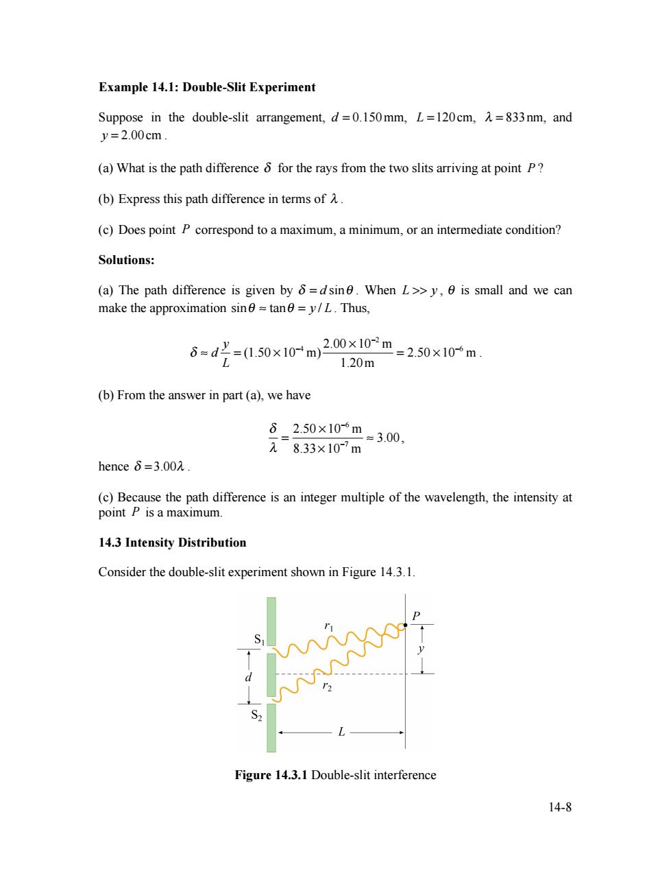
Example 14.1:Double-Slit Experiment Suppose in the double-slit arrangement,d=0.150mm,L=120cm,=833nm,and y=2.00cm. (a)What is the path difference 8 for the rays from the two slits arriving at point P? (b)Express this path difference in terms ofA. (c)Does point P correspond to a maximum,a minimum,or an intermediate condition? Solutions: (a)The path difference is given by 8=dsin.When L>>y,0 is small and we can make the approximation sin≈tanθ=y/L.Thus, 6=d'=(0.50×10-m 2.00×10-m=2.50×10m. 1.20m (b)From the answer in part(a),we have 62.50×10⁻⁶m 元8.33×10⁻⁷m =3.00, henceδ=3.002. (c)Because the path difference is an integer multiple of the wavelength,the intensity at point P is a maximum. 14.3 Intensity Distribution Consider the double-slit experiment shown in Figure 14.3.1. Figure 14.3.1 Double-slit interference 14-8
14-8 Example 14.1: Double-Slit Experiment Suppose in the double-slit arrangement, d = 0.150mm, L =120cm, λ = 833nm, and y = 2.00cm . (a) What is the path difference δ for the rays from the two slits arriving at point P ? (b) Express this path difference in terms of λ . (c) Does point P correspond to a maximum, a minimum, or an intermediate condition? Solutions: (a) The path difference is given by δ = d sinθ . When L >> y , θ is small and we can make the approximation sinθ ≈ tanθ = y / L . Thus, δ ≈ d y L = (1.50 × 10⁻⁴ m) 2.00 × 10⁻² m 1.20m = 2.50 × 10⁻⁶ m . (b) From the answer in part (a), we have δ λ = 2.50 × 10⁻⁶ m 8.33× 10⁻⁷ m ≈ 3.00, hence δ = 3.00λ . (c) Because the path difference is an integer multiple of the wavelength, the intensity at point P is a maximum. 14.3 Intensity Distribution Consider the double-slit experiment shown in Figure 14.3.1. Figure 14.3.1 Double-slit interference
The total instantaneous electric field E at the point P on the screen is equal to the vector sum of the two sources:E=E+E.The magnitude of the Poynting vector flux S is proportional to the square of the total field. S∝E2=(E,+E2)2=E+E+2E,·E2 (14.2.10) Taking the time-average of S,the intensity of the light at P is I=(S)∝(E〉+(E)+2(E·E,〉 (14.2.11) The term 2EE2)represents the correlation between the two light waves.For incoherent light sources,since there is no definite phase relation between E and E2,the cross term vanishes,and the intensity due to the incoherent source is simply the sum of the two individual intensities, Line=+12. (14.2.12) For coherent sources,the term 2EE)is non-zero.In fact,for constructive interference,E=E,,and the resulting intensity is 1=411, (14.2.13) which is four times greater than the intensity due to a single source.When destructive interference takes place,E=-E2,andEE,and the total intensity becomes I=1-211+1=0, (14.2.14) as expected. Suppose that the waves emerged from the slits are coherent sinusoidal plane waves.Let the electric field components of the wave from slits 1 and 2 at P be given by E=E sin(ot), (14.2.15) and E2=E。sin(ot+φ), (14.2.16) respectively,where the waves from both slits are assumed to have the same amplitude Eo. For simplicity,we have chosen the point P to be the origin,so that the kx dependence in the wave function is eliminated.Because the wave from slit 2 has traveled an extra 14-9
14-9 The total instantaneous electric field E at the point P on the screen is equal to the vector sum of the two sources: E = E1 + E2 . The magnitude of the Poynting vector flux S is proportional to the square of the total field, 2 2 2 2 1 2 1 2 1 2 S ∝ E = (E + E ) = E + E + 2E ⋅E . (14.2.10) Taking the time-average of S , the intensity I of the light at P is 2 2 1 2 1 2 I = S ∝ E + E + 2 E ⋅E . (14.2.11) The term 1 2 2 E ⋅E represents the correlation between the two light waves. For incoherent light sources, since there is no definite phase relation between E1 and E2 , the cross term vanishes, and the intensity due to the incoherent source is simply the sum of the two individual intensities, inc 1 2 I = I + I . (14.2.12) For coherent sources, the term 1 2 2 E ⋅E is non-zero. In fact, for constructive interference, E1 = E2 , and the resulting intensity is 1 I = 4I , (14.2.13) which is four times greater than the intensity due to a single source. When destructive interference takes place, E1 = −E2 , and 1 2 1 E ⋅E ∝ −I , and the total intensity becomes 1 1 1 I = I − 2I + I = 0 , (14.2.14) as expected. Suppose that the waves emerged from the slits are coherent sinusoidal plane waves. Let the electric field components of the wave from slits 1 and 2 at P be given by E1 = E0 sin(ωt) , (14.2.15) and 2 0 E = E sin(ωt +φ) , (14.2.16) respectively, where the waves from both slits are assumed to have the same amplitude E0 . For simplicity, we have chosen the point P to be the origin, so that the kx dependence in the wave function is eliminated. Because the wave from slit 2 has traveled an extra
distance 8 to P,E2 has an extra phase constant o relative to E,which traveled from slit 1. For constructive interference,a path difference of 8=A would correspond to a phase shift of o=2.This implies that the ratio of path difference to wavelength is equal to the ratio of phase shift to2π, 60 (14.2.17) 12π Therefore the phase shift is 0= 61 dsine. (14.2.18) Assuming that both fields point in the same direction,the total electric field may be obtained by using the superposition principle discussed in Section 13.5, E=E+E2=E[sin(@t)+sin(@t+)=2E cos(/2)sin(t+/2)(14.2.19) where we have used the trigonometric identity sina+sinB=2sin m (14.2.20) The intensity I is proportional to the time-average of the square of the total electric field, I(E2)=4E2cos(/2)(sin(@t+/2)=2Ecos(/2). (14.2.21) Therefore the intensity is 1=1cos2(0/2), (14.2.22) where /o is the maximum intensity on the screen.Substitute Eq.(14.2.18)into Eq. (14.2.22)yielding I=Icos(πdsin6/) (14.2.23) The plot of the ratio I/I as a function of dsine/A is shown in Figure 14.3.2. 14-10
14-10 distance δ to P , E2 has an extra phase constant φ relative to E1 , which traveled from slit 1. For constructive interference, a path difference of δ = λ would correspond to a phase shift of φ = 2π . This implies that the ratio of path difference to wavelength is equal to the ratio of phase shift to 2π , 2 δ φ λ π = . (14.2.17) Therefore the phase shift is 2 2 d sin π π φ δ θ λ λ = = . (14.2.18) Assuming that both fields point in the same direction, the total electric field may be obtained by using the superposition principle discussed in Section 13.5, E = E1 + E2 = E0 ⎡sin(ωt) + sin(ωt + φ) ⎣ ⎤ ⎦ = 2E0 cos(φ / 2)sin(ωt + φ / 2) (14.2.19) where we have used the trigonometric identity sinα + sinβ = 2sin α + β 2 ⎛ ⎝ ⎜ ⎞ ⎠ ⎟ cos α − β 2 ⎛ ⎝ ⎜ ⎞ ⎠ ⎟ . (14.2.20) The intensity I is proportional to the time-average of the square of the total electric field, I ∝ E2 = 4E0 2 cos2 (φ / 2) sin2 (ωt + φ / 2) = 2E0 2 cos2 (φ / 2). (14.2.21) Therefore the intensity is I = I0 cos2 (φ / 2) , (14.2.22) where 0 I is the maximum intensity on the screen. Substitute Eq. (14.2.18) into Eq. (14.2.22) yielding I = I0 cos2 (πd sinθ / λ) . (14.2.23) The plot of the ratio I / I0 as a function of d sinθ / λ is shown in Figure 14.3.2