(a) 6 Bulky solids 3D solid element mesh Neutral surface Shell 2D shell element mesh Neutral surface Centroid Beam member ID beam element mesh Geometrical modeling.(a)Physical geometry of the structural parts;(b)geometry created in FEM models
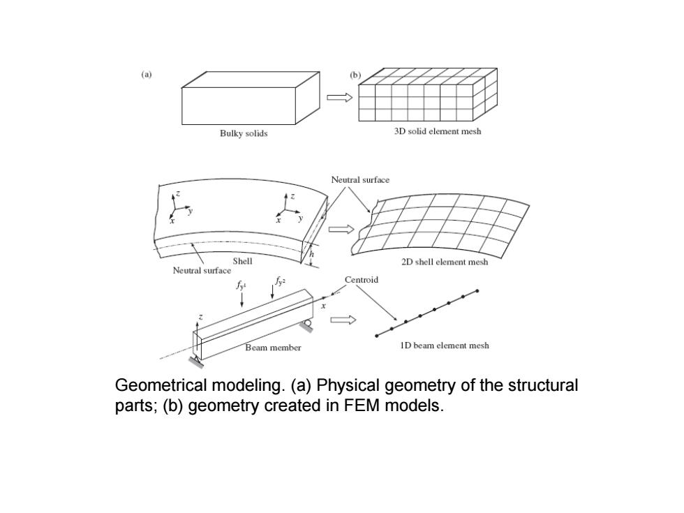
Geometrical modeling. (a) Physical geometry of the structural parts; (b) geometry created in FEM models
PRACTICAL CONSIDERATION Probably the most critical step in application of the finite element method is the choice of element type for a given problem.The solid elements discussed so far are among the simplest elements available for use in FEM analysis.Many more element types are available to the finite element analyst.(One commercial software system has no fewer than 141 element types.)The differences in elements for FEM (e.g.stress) analysis fall into three categories: (1)number of nodes,hence,polynomial order of interpolation functions; (2)type of material behavior (elastic,plastic,thermal stress,for example);and (3)loading and geometry of the structure to be modeled(plane stress,plane strain, axisymmetric,general three dimensional,bending,torsion)
PRACTICAL CONSIDERATION Probably the most critical step in application of the finite element method is the choice of element type for a given problem. The solid elements discussed so far are among the simplest elements available for use in FEM analysis. Many more element types are available to the finite element analyst. (One commercial software system has no fewer than 141 element types.) The differences in elements for FEM (e.g. stress) analysis fall into three categories: (1) number of nodes, hence, polynomial order of interpolation functions; (2) type of material behavior (elastic, plastic, thermal stress, for example); and (3) loading and geometry of the structure to be modeled (plane stress, plane strain, axisymmetric, general three dimensional, bending, torsion)
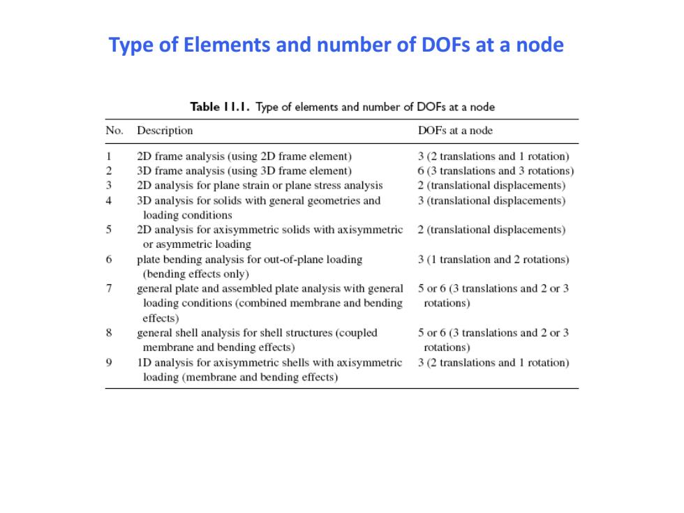
Type of Elements and number of DOFs at a node Table I 1.I.Type of elements and number of DOFs at a node No.Description DOFs at a node 1 2D frame analysis (using 2D frame element) 3(2 translations and 1 rotation) 2 3D frame analysis (using 3D frame element) 6(3 translations and 3 rotations) 3 2D analysis for plane strain or plane stress analysis 2 (translational displacements) 4 3D analysis for solids with general geometries and 3 (translational displacements) loading conditions 2D analysis for axisymmetric solids with axisymmetric 2 (translational displacements) or asymmetric loading 6 plate bending analysis for out-of-plane loading 3(1 translation and 2 rotations) (bending effects only) 1 general plate and assembled plate analysis with general 5 or 6(3 translations and 2 or 3 loading conditions (combined membrane and bending rotations) effects) general shell analysis for shell structures (coupled 5 or 6(3 translations and 2 or 3 membrane and bending effects) rotations) ID analysis for axisymmetric shells with axisymmetric 3(2 translations and 1 rotation) loading (membrane and bending effects)
Type of Elements and number of DOFs at a node
Element Distortions Five possible forms of element distortions and their rough limits are listed as follows: 1.Aspect ratio distortion (elongation of element). 2.Angular distortion of the element,where any included angle between edges approaches either0。or180。(skew and taper). 3.Curvature distortion of element,where the straight edges from the element are distorted into curves when matching the nodes to the geometric points. 4.Volumetric distortion occurs in concave elements.As discussed in calculating the element stiffness matrix,a mapping is performed in order to transfer the irregular shape of the element in the physical coordinate system into a regular one in the non-dimensional natural coordinate system.For concave elements,there are areas outside the elements (see the shadowed area in Figure)that will be transformed into an internal area in the natural coordinate system.The element volume integration for the shadowed area based on the natural coordinate system will thus result in a negative value.A few unacceptable shapes of quadrilateral elements are shown in Figure. 5.Mid-node position distortion occurs with higher order elements where there are mid nodes.The mid node should be placed as close as possible to the middle of the element edge.The limit for mid-node displacement away from the middle edge of the element is a quarter of the element edge,as shown in Figure.The reason is that this shifting of mid nodes can result in a singular stress field in the elements. Many FEM package preprocessors provide a tool for analysing the element distortion rate for a created mesh.All the user needs to do is invoke the tool after the mesh has been created before submitting it for analysis.A report of the distortion rates will be generated for the analyst's examination
Five possible forms of element distortions and their rough limits are listed as follows: 1. Aspect ratio distortion (elongation of element) . 2. Angular distortion of the element , where any included angle between edges approaches either 0◦ or 180◦ (skew and taper). 3. Curvature distortion of element, where the straight edges from the element are distorted into curves when matching the nodes to the geometric points. 4. Volumetric distortion occurs in concave elements. As discussed in calculating the element stiffness matrix, a mapping is performed in order to transfer the irregular shape of the element in the physical coordinate system into a regular one in the non-dimensional natural coordinate system. For concave elements, there are areas outside the elements (see the shadowed area in Figure) that will be transformed into an internal area in the natural coordinate system. The element volume integration for the shadowed area based on the natural coordinate system will thus result in a negative value. A few unacceptable shapes of quadrilateral elements are shown in Figure. 5. Mid-node position distortion occurs with higher order elements where there are mid nodes. The mid node should be placed as close as possible to the middle of the element edge. The limit for mid-node displacement away from the middle edge of the element is a quarter of the element edge, as shown in Figure. The reason is that this shifting of mid nodes can result in a singular stress field in the elements. Many FEM package preprocessors provide a tool for analysing the element distortion rate for a created mesh. All the user needs to do is invoke the tool after the mesh has been created before submitting it for analysis. A report of the distortion rates will be generated for the analyst’s examination. Element Distortions
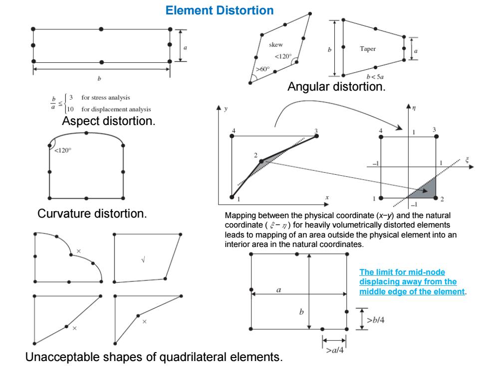
Element Distortion skew <120 >609 b b<5a Angular distortion. 名子6知 Aspect distortion. <120 Curvature distortion. Mapping between the physical coordinate(x-y)and the natural coordinate (-for heavily volumetrically distorted elements leads to mapping of an area outside the physical element into an interior area in the natural coordinates. The limit for mid-node displacing away from the 0 middle edge of the element. 6 >b/4 Unacceptable shapes of quadrilateral elements
Aspect distortion. Angular distortion. Curvature distortion. Mapping between the physical coordinate (x−y) and the natural coordinate (ξ−η) for heavily volumetrically distorted elements leads to mapping of an area outside the physical element into an interior area in the natural coordinates. Unacceptable shapes of quadrilateral elements. The limit for mid-node displacing away from the middle edge of the element. Element Distortion