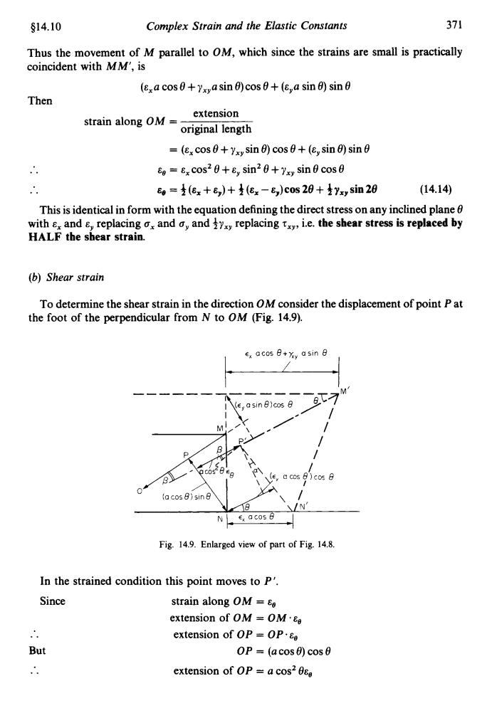
§14.10 Complex Strain and the Elastic Constants 371 Thus the movement of M parallel to OM,which since the strains are small is practically coincident with MM',is (xa cos0+Yxa sin 0)cos0+(E,a sin 0)sin0 Then strain along OM= extension original length =(ex cos0+Yx,sin 0)cos+(Ey sin 0)sin0 Eo=Ex cos20+sin20+Yxy sin 0 cos g=支(ex+e,)+(ex-e,)c0s20+是Yxy sin28 (14.14) This is identical in form with the equation defining the direct stress on any inclined plane with &x and E,replacing ox and a,and ty replacing tx,i.e.the shear stress is replaced by HALF the shear strain. (b)Shear strain To determine the shear strain in the direction OM consider the displacement of point P at the foot of the perpendicular from N to OM(Fig.14.9). Ex QCOs8+y asin日 ey a sin B)cos 8 D (e,a cos B)cos 8 la cos 8)sin8 N E acos Fig.14.9.Enlarged view of part of Fig.14.8. In the strained condition this point moves to p'. Since strain along OM extension of OM=OM·eg extension of OP=OP·eg But OP (acos0)cos0 extension of OP a cos2 0eg
$14.10 Complex Strain and the Elastic Constants 37 1 Thus the movement of M parallel to OM, which since the strains are small is practically coincident with MM', is (&,a cos 8 + y,,a sin 0)cos 8 + (&,a sin 6) sin 8 Then extension original length strain along OM = = (E, cos 0 + yxy sin e) cos 8 + (ey sin e) sin 8 .. E, = E, cosz e + E, sinZ e + yxy sin e cos e .. Eo = 3 (E, + E,,) + 3 (E, - E,,) cos 28 + 3 yxp sin 28 (14.14) This is identical in form with the equation defining the direct stress on any inclined plane 8 with E, and cy replacing ox and oy and &J,, replacing T,~, i.e. the shear stress is replaced by HALF the shear strain. (b) Shear strain To determine the shear strain in the direction OM consider the displacement of point P at the foot of the perpendicular from N to OM (Fig. 14.9). w cX acos B+X, asin 9 Fig. 14.9. Enlarged view of part of Fig. 14.8. In the strained condition this point moves to P' Since But .. strain along OM = E, extension of OM = OM extension of OP = OP~E, extension of OP = a cosz eEo OP = (a COS e) COS e

372 Mechanics of Materials §14.11 During straining the line PN rotates counterclockwise through a small angle a. (exacos 0)cos0-acos20e acos 0 sin0 =(Ex-Ee)cot0 The line OM also rotates,but clockwise,through a small angle B=(xacos+asin)sin-(e,asin)cos Thus the required shear strain ye in the direction OM,i.e.the amount by which the angle OPN changes,is given by Yo=+B=(Ex-Eo)cot+(Ex cos0+Yx>sin0)sin 0-E sin e cos0 Substituting for 8e from egn.(14.14)gives yg=2(ex-e,)cosθsin6-yxy(cos2θ-sin2) Ye=(ex-e)sin 20-1Yxy cos 20 which again is similar in form to the expression for the shear stress t on any inclined plane 0. For consistency of sign convention,however (see $14.11 below),because OM'moves clockwise with respect to OM it is considered to be a negative shear strain,i.e. 生Ya=-[(ex-e,)sin28-生yx,cos20] (14.15) 14.11.Principal strain-Mohr's strain circle Since the equations for stress and strain on oblique planes are identical in form,as noted above,it is evident that Mohr's stress circle construction can be used equally well to represent strain conditions using the horizontal axis for linear strains and the vertical axis for half the shear strain.It should be noted,however,that angles given by Mohr's stress circle refer to the directions of the planes on which the stresses act and not to the direction of the stresses themselves.The directions of the stresses and hence the associated strains are therefore normal (i.e.at 90)to the directions of the planes.Since angles are doubled in Mohr's circle construction it follows therefore that for true similarity of working a relative rotation of the axes of 2 x 90=180 must be introduced.This is achieved by plotting positive shear strains vertically downwards on the strain circle construction as shown in Fig.14.10. Fig.14.10.Mohr's strain circle
372 Mechanics of Materials 614.1 1 During straining the line PN rotates counterclockwise through a small angle u. (&,a cos e) cos e - a cos2 8Ee a cos 8 sin 8 U= = (E, -Ee) cot 8 The line OM also rotates, but clockwise, through a small angle (&,a cos 8 + yxya sin 8) sin 8 - (&,a sin 8) cos 8 a B= Thus the required shear strain Ye in the direction OM, i.e. the amount by which the angle OPN changes, is given by ye = u + B = (E, - Ee)cot 8 + (E,COS 8 + y,,sin 8)sin 8 - &,sin 8 cos 8 Ye = 2 (E, - E,) cos e sin 8 - yxy (cos2 e - sin2 e) Substituting for from eqn. (14.14) gives .. which again is similar in form to the expression for the shear stress ‘t on any inclined plane e. For consistency of sign convention, however (see 6 14.1 1 below), because OM’ moves clockwise with respect to OM it is considered to be a negative shear strain, Le. 370 = 3 (E, - E,) sin 28 -$y,, cos 28 +ye = -[3(~,-&~)~i02e-+y~,~0~28] (14.H) 14.11. Principal strain- Mohr’s strain circle Since the equations for stress and strain on oblique planes are identical in form, as noted above, it is evident that Mohr’s stress circle construction can be used equally well to represent strain conditions using the horizontal axis for linear strains and the vertical axis for halfthe shear strain. It should be noted, however, that angles given by Mohr’s stress circle refer to the directions of the planes on which the stresses act and not to the direction of the stresses themselves. The directions of the stresses and hence the associated strains are therefore normal @e. at 90”) to the directions of the planes. Since angles are doubled in Mohr’s circle construction it follows therefore that for true similarity of working a relative rotation of the axes of 2 x 90 = 180” must be introduced. This is achieved by plotting positive shear strains vertically downwards on the strain circle construction as shown in Fig. 14.10. 0 + +Y Fig. 14.10. Mohr’s strain circle
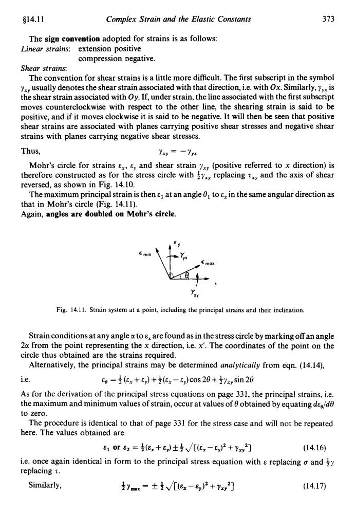
§14.11 Complex Strain and the Elastic Constants 373 The sign convention adopted for strains is as follows: Linear strains:extension positive compression negative. Shear strains: The convention for shear strains is a little more difficult.The first subscript in the symbol usually denotes the shear strain associated with that direction,i.e.with Ox.Similarly,xis the shear strain associated with Oy.If,under strain,the line associated with the first subscript moves counterclockwise with respect to the other line,the shearing strain is said to be positive,and if it moves clockwise it is said to be negative.It will then be seen that positive shear strains are associated with planes carrying positive shear stresses and negative shear strains with planes carrying negative shear stresses. Thus, yxy=一yx Mohr's circle for strains x,and shear strain (positive referred to x direction)is therefore constructed as for the stress circle with replacing and the axis of shear reversed,as shown in Fig.14.10. The maximum principal strain is then at an angle 0 to e,in the same angular direction as that in Mohr's circle (Fig.14.11). Again,angles are doubled on Mohr's circle. Fig.14.11.Strain system at a point,including the principal strains and their inclination. Strain conditions at any angle a to E are found as in the stress circle by marking off an angle 2a from the point representing the x direction,i.e.x'.The coordinates of the point on the circle thus obtained are the strains required. Alternatively,the principal strains may be determined analytically from eqn.(14.14), i.e. Eo=(Ex+)+(Ex-E)cos 20+Yxy sin 20 As for the derivation of the principal stress equations on page 331,the principal strains,i.e. the maximum and minimum values of strain,occur at values of 0 obtained by equating dee/de to zero. The procedure is identical to that of page 331 for the stress case and will not be repeated here.The values obtained are c1or2=(ex+e,)±克√/[ex-e,)2+y2] (14.16) i.e.once again identical in form to the principal stress equation with replacing o and y replacing t. Similarly, x=(ex-)2+Ys2] (14.17)
$14.1 1 Complex Strain and the Elastic Constants 373 The sign convention adopted for strains is as follows: Linear strains: extension positive Shear strains: The convention for shear strains is a little more difficult. The first subscript in the symbol y,,, usually denotes the shear strain associated with that direction, i.e. with Ox. Similarly, y,,, is the shear strain associated with Oy. If, under strain, the line associated with the first subscript moves counterclockwise with respect to the other line, the shearing strain is said to be positive, and if it moves clockwise it is said to be negative. It will then be seen that positive shear strains are associated with planes carrying positive shear stresses and negative shear strains with planes carrying negative shear stresses. compression negative. Thus, Yxy = -Yyx Mohr’s circle for strains E,, E,, and shear strain y,,, (positive referred to x direction) is therefore constructed as for the stress circle with iy,, replacing 7,,, and the axis of shear reversed, as shown in Fig. 14.10. The maximum principal strain is then E, at an angle 8, to E, in the same angular direction as that in Mohr’s circle (Fig. 14.11). Again, angles are doubled on Mohr’s circle. YXY Fig. 14.1 1. Strain system at a point, including the principal strains and their inclination. Strain conditions at any angle a to E, are found as in the stress circle by marking off an angle 2u from the point representing the x direction, i.e. x’. The coordinates of the point on the circle thus obtained are the strains required. Alternatively, the principal strains may be determined analytically from eqn. (14.14), i.e. E, = 3 (E, + E,,) + +(E, - E,,) cos 28 + iy,, sin 28 As for the derivation of the principal stress equations on page 331, the principal strains, i.e. the maximum and minimum values of strain, occur at values of 8 obtained by equating ds,/d8 to zero. The procedure is identical to that of page 331 for the stress case and will not be repeated here. The values obtained are E1 or E2 = +(E, + cy) k 3 JCt% - q2 + Yxy21 i.e. once again identical in form to the principal stress equation with E replacing 0 and +y replacing T. (14.16) Similarly, (14.17)
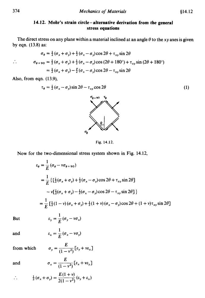
374 Mechanics of Materials S14.12 14.12.Mohr's strain circle-alternative derivation from the general stress equations The direct stress on any plane within a material inclined at an angle 0 to the xy axes is given by eqn.(13.8)as: o=(ax+)+(ox-G)cos 20+tx sin 20 0g+90=(ox+c,)+(ox-0,)cos(20+180)+txysin(20+180) =(ax+)-(ax-a)cos 20-txy sin 20 Also,from eqn.(13.9), to=(ax-)sin 20-txy cos 20 () 0日+90 Fig.14.12. Now for the two-dimensional stress system shown in Fig.14.12, 1 8g=E(og-v0g+90) =E)+(-0,)cos 20+sin20] -v[(ax+)-(ax-a)cos 20-txy sin 20]} =E[1-(ox+,)+1+9(ox-0,cos20+(1+r,sin2] 1 But ey =E(0-vo) 1 and 8=Eox-vo) E from which ,=-6,+e] E and .-[e.+e,] ∴ ox+) E(1+y 20-巧6,+e)
374 Mechanics of Materials $14.12 14.12. Mohr's strain circle-alternative derivation from the general stress equations The direct stress on any plane within a material inclined at an angle 0 to the xy axes is given by eqn. (13.8) as: ag = $ (a, + a,) + f (a, - a,) cos 28 + zxy sin 28 .. oe+9o = 3 (0, +a,) +$ (a, - a,)cos (28 + 1800) + z,, sin (28 + 1800) = f (a, + a,) - b; (a, - a,) cos 28 - z,, sin 28 Also, from eqn. (1 3.9), zg = + (a, - 0,) sin 28 - rXy cos 28 Fig. 14.12. Now for the two-dimensional stress system shown in Fig. 14.12, 1 E - -(%-V%+90) e-E 1 E = - { [+(a, + 0,) + + (a, - a,) cos 28 + z,, sin 281 - v[$(a, + 0,) -$(a, - a,) cos 28 - z,,, sin 281 ] 1 E = - [f(1 - v) (a, +ay) +3(1+ v) (a, - a,)cos 28 + (1 + v)z,, sin 281 1 'E 1 E E =-(a,-va,) E, = - (a, - va,) a, = ____ [E, + YEXI (1 - v2) a* = ~ [E, + YE, 3 (1 - VZ) But and E from which E and E(l+v) .. 3 (a, + by) = 2(1 - v2) (CY + Ex)