
盒 AO TONG U MT333 Materials Applications and Practice Superalloys in Aerospace A.Superalloys and Applications B.Superalloys Additive Manufacturing C.Superalloys Subtractive Manufacturing MT333 Materials Applications Practice Prof.XiaoQi Chen c.1 Superalloys Additive Manufacturing O TONG U Learning Goals 1.Understand and apply adaptive machining of superalloys 2.Understand and apply 3D Grinding of superalloys 3.Understand Concept of Material Removal Model MT333 Materials Applications&Practice Prof.XiaoQi Chen C.2
MT333 Materials Applications C.1 & Practice Prof. XiaoQi Chen MT333 Materials Applications and Practice A. Superalloys and Applications B. Superalloys Additive Manufacturing C. Superalloys Subtractive Manufacturing Superalloys in Aerospace MT333 Materials Applications C.2 & Practice Prof. XiaoQi Chen Superalloys Additive Manufacturing 1. Understand and apply adaptive machining of superalloys 2. Understand and apply 3D Grinding of superalloys 3. Understand Concept of Material Removal Model Learning Goals
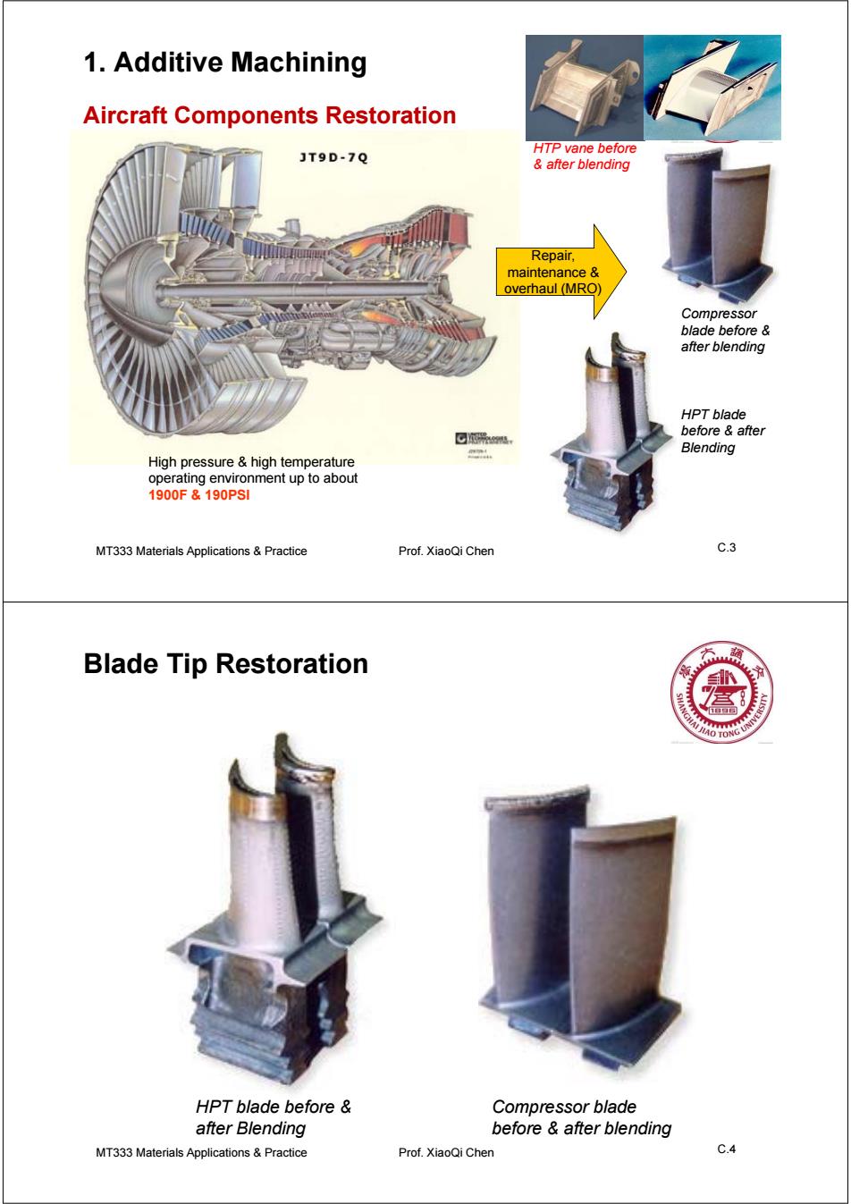
1.Additive Machining Aircraft Components Restoration JT9D-7Q HTP vane before after blending Repair. maintenance overhaul (MRO) Compressor blade before after blending HPT blade before after Blending High pressure high temperature operating environment up to about 1900F&190PSI MT333 Materials Applications Practice Prof.XiaoQi Chen C.3 Blade Tip Restoration O TONG UN HPT blade before Compressor blade after Blending before after blending MT333 Materials Applications&Practice Prof.XiaoQi Chen C.4
MT333 Materials Applications C.3 & Practice Prof. XiaoQi Chen 1. Additive Machining HPT blade before & after Blending Compressor blade before & after blending HTP vane before & after blending High pressure & high temperature operating environment up to about 1900F & 190PSI Repair, maintenance & overhaul (MRO) Aircraft Components Restoration MT333 Materials Applications C.4 & Practice Prof. XiaoQi Chen Blade Tip Restoration HPT blade before & after Blending Compressor blade before & after blending
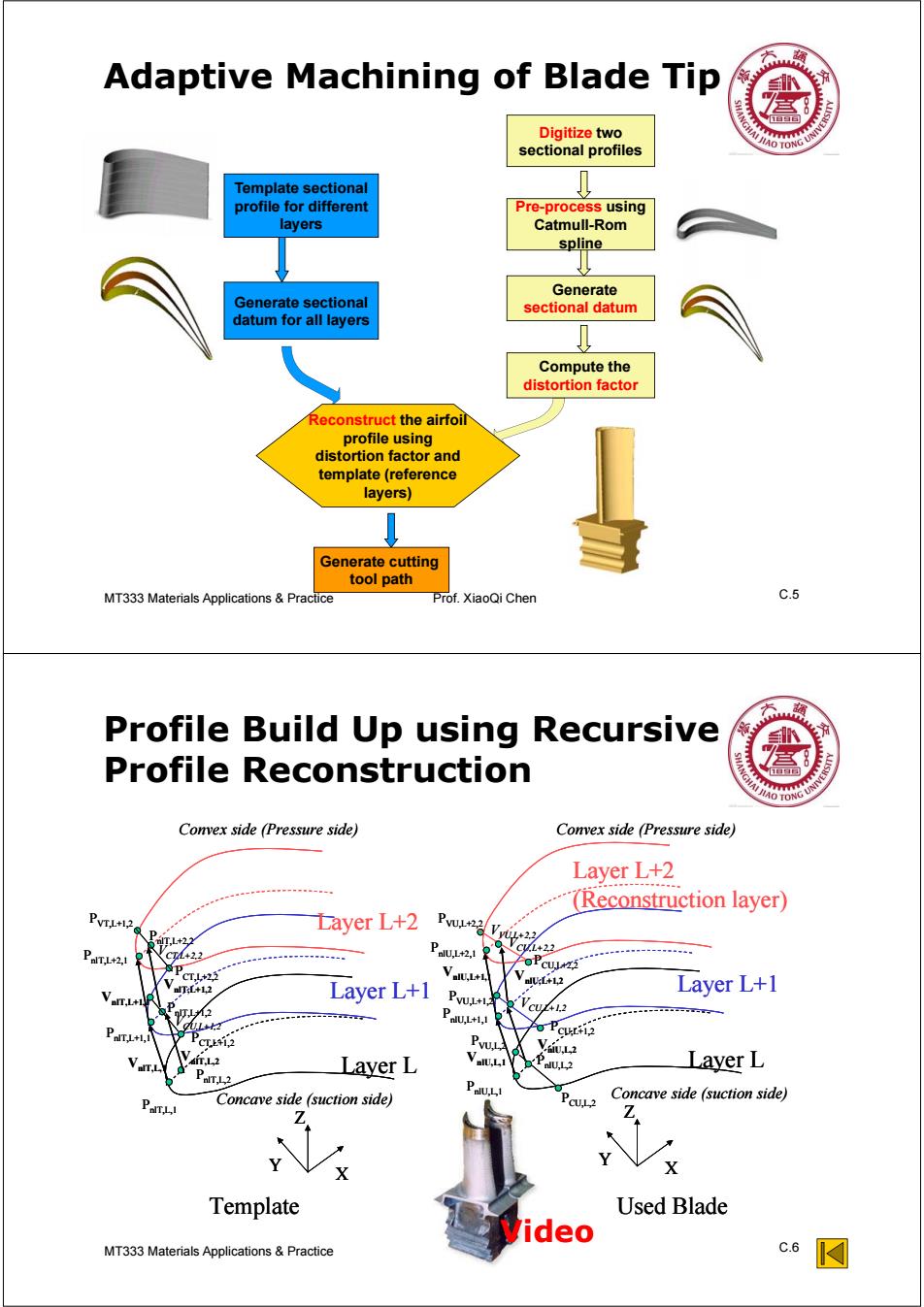
Adaptive Machining of Blade Tip 盒 Digitize two sectional profiles Template sectional profile for different Pre-process using layers Catmull-Rom spline Generate Generate sectional sectional datum datum for all layers ↓ Compute the distortion factor Reconstruct the airfoil profile using distortion factor and template (reference layers) Generate cutting tool path MT333 Materials Applications Practice Prof.XiaoQi Chen c.5 Profile Build Up using Recursive Profile Reconstruction Convex side (Pressure side) Convex side (Pressure side) Layer L+2 (Reconstruction layer) PVTL+12 Dayer L+2 TL+22 PaTL+21 PaUL2 CL+22 VaIU.L+L FoPcuwzi CT.L+22 alU:L+12 Layer L+1 Van.i+ olT:L+L2 Layer L+1 ,2 PaU.L+11 +l. o PCUL+i2 CT1,2 V,2 Layer L PaT12 Layer L Concave side (suction side) Concave side (suction side) Z Template Used Blade ideo MT333 Materials Applications&Practice C.6 ☑
MT333 Materials Applications C.5 & Practice Prof. XiaoQi Chen Adaptive Machining of Blade Tip Template sectional profile for different layers Digitize two sectional profiles Generate sectional datum for all layers Generate sectional datum Compute the distortion factor Generate cutting tool path Reconstruct the airfoil profile using distortion factor and template (reference layers) Pre-process using Catmull-Rom spline MT333 Materials Applications C.6 & Practice Prof. XiaoQi Chen Profile Build Up using Recursive Profile Reconstruction VnlU,L+1,1 VnlU,L,1 Layer L Layer L+2 (Reconstruction layer) Layer L+1 VCU,L+1,2 VCU,L+2,2 VnlT,L,1 VnlT,L+1,1 Layer L Layer L+2 Layer L+1 PnlT,L,1 PnlT,L+1,1 PnlT,L+2,1 Template Used Blade PnlT,L,2 PnlT,L+1,2 PVT,L+1,2 VnlT,L,2 VnlT,L+1,2 VnlU,L,2 VnlU,L+1,2 PCU,L,2 PCU,L+1,2 PCU,L+2,2 VVU,L+2,2 PVU,L+2,2 PnlU,L,1 PnlU,L+1,1 PnlU,L+2,1 X Z Y X Z Y Convex side (Pressure side) Concave side (suction side) Concave side (suction side) Convex side (Pressure side) PVU,L,2 PVU,L+1,2 PnlU,L,2 PCT,L+1,2 PnlT,L+2,2 PCT,L+2,2 VCU,L+1,2 VCT,L+2,2 VnlU,L+1,1 VnlU,L,1 Layer L Layer L+2 (Reconstruction layer) Layer L+1 VCU,L+1,2 VCU,L+2,2 VnlT,L,1 VnlT,L+1,1 Layer L Layer L+2 Layer L+1 PnlT,L,1 PnlT,L+1,1 PnlT,L+2,1 Template Used Blade PnlT,L,2 PnlT,L+1,2 PVT,L+1,2 VnlT,L,2 VnlT,L+1,2 VnlU,L,2 VnlU,L+1,2 PCU,L,2 PCU,L+1,2 PCU,L+2,2 VVU,L+2,2 PVU,L+2,2 PnlU,L,1 PnlU,L+1,1 PnlU,L+2,1 X Z Y X Z Y Convex side (Pressure side) Concave side (suction side) Concave side (suction side) Convex side (Pressure side) PVU,L,2 PVU,L+1,2 PnlU,L,2 PCT,L+1,2 PnlT,L+2,2 PCT,L+2,2 VCU,L+1,2 VCT,L+2,2 Video
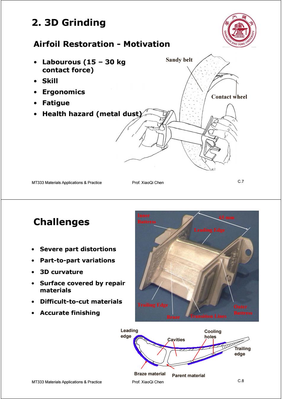
2.3D Grinding Airfoil Restoration Motivation JIAO TO ONG UN ·Labourous(15-30kg Sandy belt contact force) 。Skill ·Ergonomics Contact wheel ·Fatigue Health hazard (metal dust) MT333 Materials Applications Practice Prof.XiaoQi Chen C.7 Inner 65 mm Challenges Buttress Leading Edge Severe part distortions Part-to-part variations ·3 D curvature Surface covered by repair materials Difficult-to-cut materials Trailing Edge Oufer ·Accurate finishing Buttress Braze ansition Lines Leading Cooling edge holes Cavities Trailing edge Braze material Parent material MT333 Materials Applications&Practice Prof.XiaoQi Chen C.8
MT333 Materials Applications C.7 & Practice Prof. XiaoQi Chen 2. 3D Grinding Contact wheel Sandy belt • Labourous (15 – 30 kg contact force) • Skill • Ergonomics • Fatigue • Health hazard (metal dust) Airfoil Restoration - Motivation MT333 Materials Applications C.8 & Practice Prof. XiaoQi Chen Challenges 65 mm Trailing Edge Leading Edge Braze Outer Buttress Inner Buttress Transition Lines Braze material Parent material Leading edge Trailing edge Cavities Cooling holes • Severe part distortions • Part-to-part variations • 3D curvature • Surface covered by repair materials • Difficult-to-cut materials • Accurate finishing
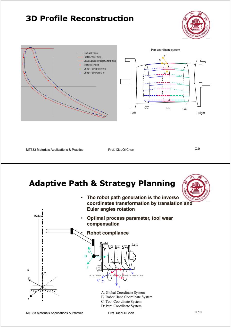
3D Profile Reconstruction 盒 AO TO Part coordinate system 一Design Profile Profile After Fitting Leading Edge Height After Fiting Measure Points Check Point Betore Cut Check Point ARer Cut GG Left Right MT333 Materials Applications Practice Prof.XiaoQi Chen c.9 Adaptive Path Strategy Planning The robot path generation is the inverse HO TONG UNN coordinates transformation by translation and Euler angles rotation Roboi Optimal process parameter,tool wear compensation Robot compliance Right GG EE Left 7 A:Global Coordinate System B:Robot Hand Coordinate System C:Tool Coordinate System D:Part Coordinate System MT333 Materials Applications&Practice Prof.XiaoQi Chen C.10
MT333 Materials Applications C.9 & Practice Prof. XiaoQi Chen 3D Profile Reconstruction CC EE GG x y z Part coordinate system Left Right MT333 Materials Applications C.10 & Practice Prof. XiaoQi Chen Adaptive Path & Strategy Planning x z y x y z x z y x y z GG EE CC A B C D A: Global Coordinate System B: Robot Hand Coordinate System C: Tool Coordinate System D: Part Coordinate System Robot Left Right • The robot path generation is the inverse coordinates transformation by translation and Euler angles rotation • Optimal process parameter, tool wear compensation • Robot compliance