盒 AO TONG U MT333 Materials Applications and Practice Superalloys in Aerospace A.Superalloys and Applications B.Superalloys Additive Manufacturing C.Superalloys Subtractive Manufacturing MT333 Materials Applications Practice Prof.XiaoQi Chen B.1 SUPERALLOYS ADDITIVE MANUFACTURING O TONG UN Learning Goals 1.Understand AM 2.Understand Metallic AM Systems 3.Understand Technology Challenges 4.Ability to design a solution:Project Case MT333 Materials Applications Practice Prof.XiaoQi Chen B.2
MT333 Materials Applications B.1 & Practice Prof. XiaoQi Chen MT333 Materials Applications and Practice A. Superalloys and Applications B. Superalloys Additive Manufacturing C. Superalloys Subtractive Manufacturing Superalloys in Aerospace MT333 Materials Applications B.2 & Practice Prof. XiaoQi Chen SUPERALLOYS ADDITIVE MANUFACTURING 1. Understand AM 2. Understand Metallic AM Systems 3. Understand Technology Challenges 4. Ability to design a solution: Project Case Learning Goals
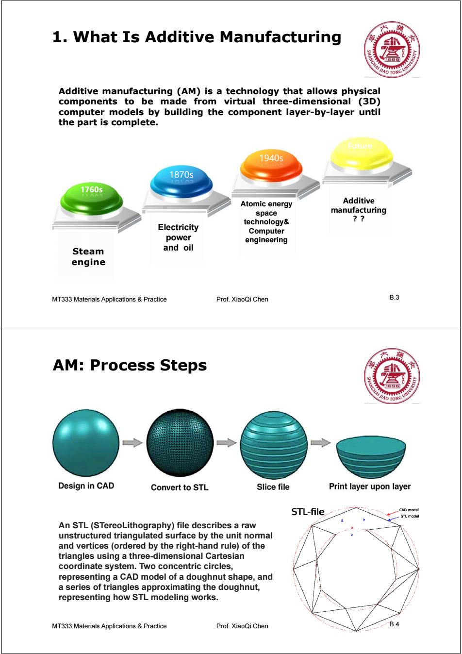
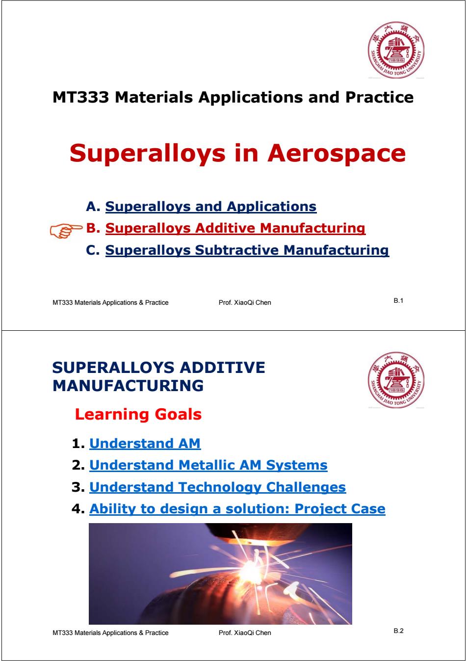
1.What Is Additive Manufacturing JIAO TO ONG UN Additive manufacturing (AM)is a technology that allows physical components to be made from virtual three-dimensional (3D) computer models by building the component layer-by-layer until the part is complete. 1940s 1870s 17605 Atomic energy Additive space manufacturing technology& ?? Electricity Computer power engineering Steam and oil engine MT333 Materials Applications Practice Prof.XiaoQi Chen B.3 AM:Process Steps O TONG UN Design in CAD Convert to STL Slice file Print layer upon layer STL-file CAD model STL model An STL(STereoLithography)file describes a raw unstructured triangulated surface by the unit normal and vertices (ordered by the right-hand rule)of the triangles using a three-dimensional Cartesian coordinate system.Two concentric circles, representing a CAD model of a doughnut shape,and a series of triangles approximating the doughnut, representing how STL modeling works. MT333 Materials Applications Practice Prof.XiaoQi Chen B.4
MT333 Materials Applications B.3 & Practice Prof. XiaoQi Chen 1760s 1870s 1940s Steam engine Electricity power and oil Atomic energy space technology& Computer engineering Additive manufacturing ?? Future 1. What Is Additive Manufacturing Additive manufacturing (AM) is a technology that allows physical components to be made from virtual three-dimensional (3D) computer models by building the component layer-by-layer until the part is complete. MT333 Materials Applications B.4 & Practice Prof. XiaoQi Chen AM: Process Steps An STL (STereoLithography) file describes a raw unstructured triangulated surface by the unit normal and vertices (ordered by the right-hand rule) of the triangles using a three-dimensional Cartesian coordinate system. Two concentric circles, representing a CAD model of a doughnut shape, and a series of triangles approximating the doughnut, representing how STL modeling works
AM:Comparison with SM Subtractive manufacturing Additive manufacturing start with a block of material ◆start with nothing remove any unwanted material add material we wanted carve it by hand or by using a build the part one layer(microns up to around machine such as a CNC 0.25 mm)at a time by 'printing'each new layer on top of the previous one,until the part is complete. MT333 Materials Applications Practice Prof.XiaoQi Chen B.5 Need for Cladding and AM A lot of the repair and restoration needs: ·Aerospace ·Power Generation ·Oil/Gas MT333 Materials Applications&Practice Prof.XiaoQi Chen B.6
MT333 Materials Applications B.5 & Practice Prof. XiaoQi Chen AM: Comparison with SM Subtractive manufacturing : start with a block of material remove any unwanted material carve it by hand or by using a machine such as a CNC Additive manufacturing : start with nothing add material we wanted build the part one layer (microns up to around 0.25 mm) at a time by ‘printing’ each new layer on top of the previous one, until the part is complete. MT333 Materials Applications B.6 & Practice Prof. XiaoQi Chen Need for Cladding and AM • Aerospace • Power Generation • Oil/Gas A lot of the repair and restoration needs:
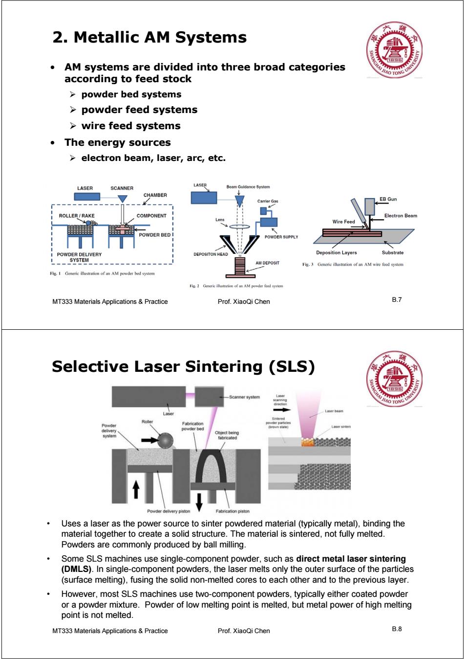
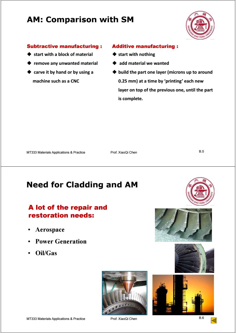
2.Metallic AM Systems AM systems are divided into three broad categories HAO TO ONG UN according to feed stock >powder bed systems powder feed systems >wire feed systems ●The energy sources >electron beam,laser,arc,etc. LASER SCANNER LASER Beam Guidance System CHAMBER EB Gur ROLLER/RAKE COMPONENT Electron Beam Wire Feed ■ POWDER BED I POWDER SUPPLY POWDER DELIVERY Deposition Layers Substrate L-SYSTEM AM DEPOSIT Fig.3 Generic illuistmution of an AM wire feed system Fig 1 Generic illustration of an AM powder bed system Fig.2 Generic illtion of AM powder foed system MT333 Materials Applications Practice Prof.XiaoQi Chen B.7 Selective Laser Sintering (SLS) O TONG UN Fabrication powder bed Powder delivery piston Uses a laser as the power source to sinter powdered material(typically metal),binding the material together to create a solid structure.The material is sintered,not fully melted. Powders are commonly produced by ball milling. Some SLS machines use single-component powder,such as direct metal laser sintering (DMLS).In single-component powders,the laser melts only the outer surface of the particles (surface melting),fusing the solid non-melted cores to each other and to the previous layer. However,most SLS machines use two-component powders,typically either coated powder or a powder mixture.Powder of low melting point is melted,but metal power of high melting point is not melted. MT333 Materials Applications&Practice Prof.XiaoQi Chen B.8
MT333 Materials Applications B.7 & Practice Prof. XiaoQi Chen 2. Metallic AM Systems • AM systems are divided into three broad categories according to feed stock powder bed systems powder feed systems wire feed systems • The energy sources electron beam, laser, arc, etc. MT333 Materials Applications B.8 & Practice Prof. XiaoQi Chen Selective Laser Sintering (SLS) • Uses a laser as the power source to sinter powdered material (typically metal), binding the material together to create a solid structure. The material is sintered, not fully melted. Powders are commonly produced by ball milling. • Some SLS machines use single-component powder, such as direct metal laser sintering (DMLS). In single-component powders, the laser melts only the outer surface of the particles (surface melting), fusing the solid non-melted cores to each other and to the previous layer. • However, most SLS machines use two-component powders, typically either coated powder or a powder mixture. Powder of low melting point is melted, but metal power of high melting point is not melted
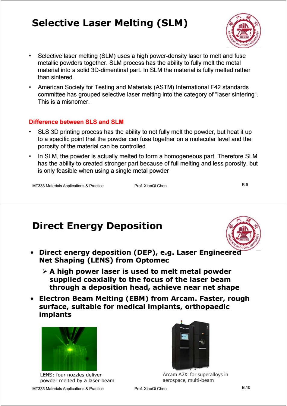
Selective Laser Melting (SLM) MAO TONG Selective laser melting(SLM)uses a high power-density laser to melt and fuse metallic powders together.SLM process has the ability to fully melt the metal material into a solid 3D-dimentinal part.In SLM the material is fully melted rather than sintered. American Society for Testing and Materials (ASTM)International F42 standards committee has grouped selective laser melting into the category of"laser sintering". This is a misnomer. Difference between SLS and SLM SLS 3D printing process has the ability to not fully melt the powder,but heat it up to a specific point that the powder can fuse together on a molecular level and the porosity of the material can be controlled. In SLM,the powder is actually melted to form a homogeneous part.Therefore SLM has the ability to created stronger part because of full melting and less porosity,but is only feasible when using a single metal powder MT333 Materials Applications Practice Prof.XiaoQi Chen B.9 Direct Energy Deposition AO TONG U ● Direct energy deposition(DEP),e.g.Laser Engineered Net Shaping (LENS)from Optomec >A high power laser is used to melt metal powder supplied coaxially to the focus of the laser beam through a deposition head,achieve near net shape Electron Beam Melting (EBM)from Arcam.Faster,rough surface,suitable for medical implants,orthopaedic implants LENS:four nozzles deliver Arcam A2X:for superalloys in powder melted by a laser beam aerospace,multi-beam MT333 Materials Applications&Practice Prof.XiaoQi Chen B.10
MT333 Materials Applications B.9 & Practice Prof. XiaoQi Chen Selective Laser Melting (SLM) • Selective laser melting (SLM) uses a high power-density laser to melt and fuse metallic powders together. SLM process has the ability to fully melt the metal material into a solid 3D-dimentinal part. In SLM the material is fully melted rather than sintered. • American Society for Testing and Materials (ASTM) International F42 standards committee has grouped selective laser melting into the category of "laser sintering“. This is a misnomer. Difference between SLS and SLM • SLS 3D printing process has the ability to not fully melt the powder, but heat it up to a specific point that the powder can fuse together on a molecular level and the porosity of the material can be controlled. • In SLM, the powder is actually melted to form a homogeneous part. Therefore SLM has the ability to created stronger part because of full melting and less porosity, but is only feasible when using a single metal powder MT333 Materials Applications B.10 & Practice Prof. XiaoQi Chen • Direct energy deposition (DEP), e.g. Laser Engineered Net Shaping (LENS) from Optomec A high power laser is used to melt metal powder supplied coaxially to the focus of the laser beam through a deposition head, achieve near net shape • Electron Beam Melting (EBM) from Arcam. Faster, rough surface, suitable for medical implants, orthopaedic implants Direct Energy Deposition LENS: four nozzles deliver powder melted by a laser beam Arcam A2X: for superalloys in aerospace, multi-beam