Compiler Directives parameter half_cycle=50; parameter stop_time 350; initial begin:clockloop /Note:clock_loop is a named block of statements clock=0; forever begin half_cycle clock=1; clock half_cycle clock=0; end end 100 200 300 initial stop_time disable clock_loop; 2021/1/13 ASIC Design,by Yan Bo 18
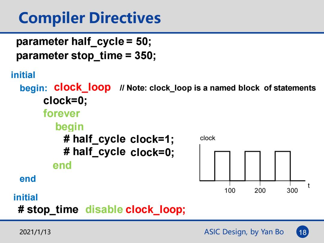
ASIC Design, by Yan Bo Compiler Directives initial begin: clock=0; forever begin # 50 clock=1; # 50 clock=0; end end clock_loop // Note: clock_loop is a named block of statements initial # 350 disable clock_loop; parameter half_cycle = 50; # half_cycle # half_cycle parameter stop_time = 350; # stop_time 2021/1/13 18
Loop Statements Used for repetitive operations -forever loop -executes continually -repeat loop -executes a fixed number of times -while loop -executes if expression is true -for loop executes once at the start of the loop and then executes if expression is true 2021/1/13 ASIC Design,by Yan Bo 19
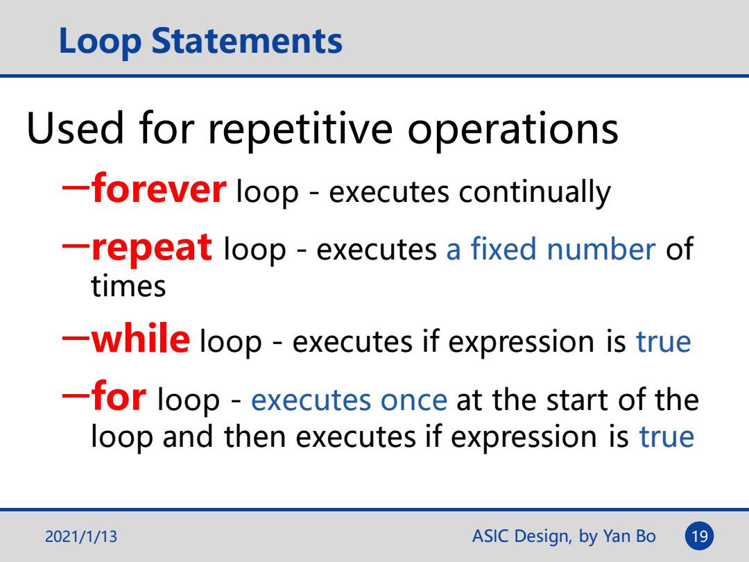
ASIC Design, by Yan Bo Loop Statements Used for repetitive operations ─forever loop - executes continually ─repeat loop - executes a fixed number of times ─while loop - executes if expression is true ─for loop - executes once at the start of the loop and then executes if expression is true 2021/1/13 19

Loop Statements(Cont.) initial begin always #50 clk=~clk Clock signal with period of 100 clk 0; time units. forever #50 clk=~clk; clock end initial begin 100 200 300 clk 0; repeat(8)#50 clk =~clk; Pulse repeats a rotate operation end 8 times. initial reg [15:0]demo_register; integer K; for (K=4;K;K=K-1) Assign bit values for a register begin 1514131211109 8 demo_register [K+10]0; demo_register [K+2]=1; 0 end 2021/1/13 ASIC Design,by Yan Bo 20
ASIC Design, by Yan Bo initial reg [15: 0] demo_register; integer K; for (K = 4; K; K = K - 1) begin demo_register [K + 10] = 0; demo_register [K + 2] = 1; end Loop Statements (Cont.) Clock signal with period of 100 time units. Pulse repeats a rotate operation 8 times. initial begin clk = 0; forever #50 clk = ~clk; end initial begin clk = 0; repeat(8) #50 clk = ~clk; end Assign bit values for a register 2021/1/13 20 always #50 clk=~clk
Topic3:Verification and Test Verilog for Testbench 。Testbench anatomy Behavioral modeling for Testbench ·Some examples Timing specification 。Delay model 。Timing verification 。Pipeline technology DFT Test vs.Verification Build In Self Test (BIST) Scan and Boundary Scan 2021/1/13 ASIC Design,by Yan Bo 21
ASIC Design, by Yan Bo Topic3: Verification and Test Verilog for Testbench • Testbench anatomy • Behavioral modeling for Testbench • Some examples Timing specification • Delay model • Timing verification • Pipeline technology DFT Test vs. Verification Build In Self Test (BIST) Scan and Boundary Scan 2021/1/13 21

Stimuli Inputs for Combinational Circuit Testing Throughout the initial a=4'b1011; simulation a initial remains constant begin After 20ns the #20b=4'b1011; simulation is finied.Allow #20b=4'b1110; At 140 ns oe changes effects of the last #20b=4'b1110; to 0 causing the y input change to output become Z #800e=1b0;<-- be shown in simulation results. #20 $finish; f changes every 23ns causing end various functions always #23 f =f+1; to be examined Name 0·1·201·30·1·40· ·50· ·60··70·1·80·1·90·t·100 120 ·130 1·150ns 0 ps B b 6 + 0 oe ASIC Design,by Yan Bo 22
ASIC Design, by Yan Bo 22 initial a=4'b1011; initial begin #20 b=4'b1011; #20 b=4'b1110; #20 b=4'b1110; #80 oe=1'b0; #20 $finish; end always #23 f = f +1; Stimuli Inputs for Combinational Circuit Testing Throughout the simulation a remains constant f changes every 23ns causing various functions to be examined At 140 ns oe changes to 0 causing the y output become Z After 20ns the simulation is finied. Allow effects of the last input change to be shown in simulation results