
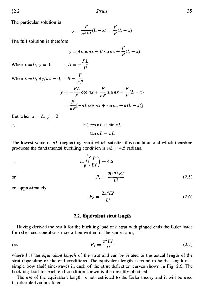
§21 Struts 33 N.B.-It is always convenient to arrange the diagram and origin such that the differential equation is achieved in the above form since the solution will then always be of the form y A cos nx+B sin nx +(particular solution) The particular solution is a particular value of y which satisfies eqn.(2.2),and in this case can be shown to be y =a. y A cos nx B sin nx+a Now whenx=0,y=0 A=-a when x =0,dy/dx =0 B=0 y =-acosnx +a But whenx=L,y=a a=-acosnL+a 0=cosnL The fundamental mode of buckling in this case therefore is given when nL = xEI or Pe= 4L2 (2.3) (c)Fixed ends Consider the strut of Fig.2.4 with the origin at the centre. Fig.2.4.Strut with fixed ends. In this case the B.M.at C is given by dx2=M-Py d2y P M dx2+Ely=Ei (D2+n2)y=M/EI
$2.1 Struts 33 N.B.-It is always convenient to arrange the diagram and origin such that the differential equation is achieved in the above form since the solution will then always be of the form y = A cos nx + B sin nx + (particular solution) The particular solution is a particular value of y which satisfies eqn. (2.2), and in this case can be shown to be y = a. .. Now when x = 0, y = 0 .. A = -a when x = 0, dyldx = 0 .. B=O .. y=-acosnx+a But when x = L, y = a .. a = -acosnL +a y = A cosnx + B sinrzx + a 0 = cosnL The fundamental mode of buckling in this case therefore is given when nL = in. or ~EI P, = - 4LZ (c) Fixed ends Consider the strut of Fig. 2.4 with the origin at the centre. Fig. 2.4. Strut with fixed ends. In this case the B.M. at C is given by (2.3) d2y P A4 dx2 El (D2 + n2)y = M/EI

34 Mechanics of Materials 2 $2.1 Here the particular solution is MM y= n2EI P y =A cos nx+Bsin nx +M/P Now when x =0,dy/dx =0..B=0 and whenx=L,y=0 )A=-M sec nL 2 M nL M y=-p sec. 2 cos nx+ But when x=L,dy/dx is also zero, 0= nM nL nL 2 别n 2 nM nL The fundamental buckling mode is then given when nL/2 =π 4x2E1 or Pa= 2 (2.4) (d)One end fixed,the other pinned In order to maintain the pin-joint on the horizontal axis of the unloaded strut,it is necessary in this case to introduce a vertical load F at the pin(Fig.2.5).The moment of F about the built-in end then balances the fixing moment. Fig.2.5.Strut with one end pinned,the other fixed. With the origin at the built-in end the B.M.at C is d2y lax=-Py+F(L-x) E F (L-x) F (D2+n2)y= L-)
34 Mechanics of Materials 2 $2.1 Here the particular solution is MM y=-- - - n2EI P .. y = Acos nx + Bsinnx + M/P Now when x = 0, dy/dx = 0 :. B = 0 1 -M nL and when x = ,L, y = 0 :.A = - sec - P 2 .. M nL M y= --sec-cosnx+- P2 P But when x = iL, dy/dx is also zero, nM nL nL 0 = ~ sec - sin - P 22 nM nL 0 = - tan - P 2 The fundamental buckling mode is then given when nL/2 = JT '&) 2 =Yt or 4dEI P, = - L= (d) One end Bed, the other pinned In order to maintain the pin-joint on the horizontal axis of the unloaded strut, it is necessary in this case to introduce a vertical load F at the pin (Fig. 2.5). The moment of F about the built-in end then balances the fixing moment. Fig. 2.5. Strut with one end pinned, the other fixed. With the origin at the built-in end the B.M. at C is d2Y dx2 d'v P F -+-y=-(L-x) Et- -Py + F(L - X) dx2 Et' EI F EI (0' + n2)y = -(L - x)
$2.2 Struts 35 The particular solution is F y-, 化-0=p化- 2EI The full solution is therefore F y=Acosnx+Bsinnx+(L-x) FL Whenx=0,y=0, ∴,A=一 P F When x=0,dy/dx=0,.'.B= nP cosnx+ FL F npsinnx+pL-划 F = np-nL cosnx+sinnx+n亿-x划 But when x=L,y=0 nL cos nL sin nL tan nL nL The lowest value of nL(neglecting zero)which satisfies this condition and which therefore produces the fundamental buckling condition is nL =4.5 radians. =45 20.25EI or P.= (2.5) L2 or,approximately 2r2E1 P.= (2.6) 2.2.Equivalent strut length Having derived the result for the buckling load of a strut with pinned ends the Euler loads for other end conditions may all be written in the same form, π2E1 i.e. P= (2.7) 12 where I is the equivalent length of the strut and can be related to the actual length of the strut depending on the end conditions.The equivalent length is found to be the length of a simple bow (half sine-wave)in each of the strut deflection curves shown in Fig.2.6.The buckling load for each end condition shown is then readily obtained. The use of the equivalent length is not restricted to the Euler theory and it will be used in other derivations later
92.2 Struts 35 The uarticular solution is F F n2EI P y=- (L-x)=-(L-x) The full solution is therefore F P y = Acosnx + Bsinnx + -(L - x) FL P When x = 0, y = 0, .A=-- .. F When x = 0, dyldx = 0, :. B = - nP F. F osnx + - sinnx + -(L - x) FL y=--c P nP P F nP = -[-nL cos nx + sin nx + n (L - x>I But when x = L, y = 0 .. nL cos nL = sin nL tannL = nL The lowest value of nL (neglecting zero) which satisfies this condition and which therefore produces the fundamental buckling condition is nL = 4.5 radians. or 20.25EI P, = ~ L* or, approximately 2.2. Equivalent strut length Having derived the result for the buckling load of a strut with pinned ends the Euler loads for other end conditions may all be written in the same form, i.e. X~EI P, = - 12 (2.7) where 1 is the equivalent length of the strut and can be related to the actual length of the strut depending on the end conditions. The equivalent length is found to be the length of a simple bow (half sine-wave) in each of the strut deflection curves shown in Fig. 2.6. The buckling load for each end condition shown is then readily obtained. The use of the equivalent length is not restricted to the Euler theory and it will be used in other derivations later
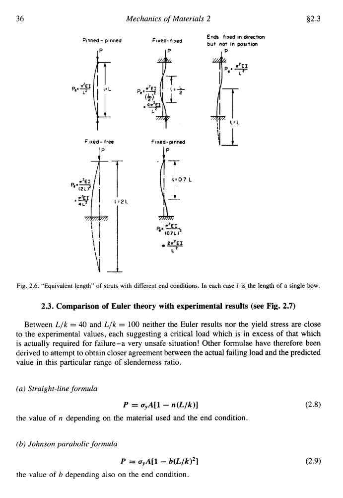
36 Mechanics of Materials 2 $2.3 Pinned-pinned Fixed-fixed Ends fixed in direction but not in position P 4m1 Fixed-free Fixed-pinned 2L7 777 70P历 R:E红 f07L)2 22虹 L Fig.2.6."Equivalent length"of struts with different end conditions.In each case is the length of a single bow. 2.3.Comparison of Euler theory with experimental results (see Fig.2.7) Between L/k =40 and L/k 100 neither the Euler results nor the yield stress are close to the experimental values,each suggesting a critical load which is in excess of that which is actually required for failure-a very unsafe situation!Other formulae have therefore been derived to attempt to obtain closer agreement between the actual failing load and the predicted value in this particular range of slenderness ratio. (a)Straight-line formula P dyA[1 n(L/k)] (2.8) the value of n depending on the material used and the end condition. (b)Johnson parabolic formula P=o,A[1-b(L/k)2] (2.9) the value of b depending also on the end condition
36 Mechanics of Materials 2 $2.3 Pinned - pinned P pe*+[ T 1 fixed-free IP fixed- fixed IP f ixed-pinned P b7 L Ends fixed in &reclan but not in position Fig. 2.6. “Equivalent length” of struts with different end conditions. In each case 1 is the length of a single bow. 23. Comparison of Euler theory with experimental results (see Fig. 2.7) Between L/k = 40 and L/k = 100 neither the Euler results nor the yield stress are close to the experimental values, each suggesting a critical load which is in excess of that which is actually required for failure-a very unsafe situation! Other formulae have therefore been derived to attempt to obtain closer agreement between the actual failing load and the predicted value in this particular range of slenderness ratio. (a) Straight-line formula P = cYA[1 - n(L/k)] the value of n depending on the material used and the end condition. (b) Johnson parabolic formula P = uyA[l - b(L/k)’] the value of b depending also on the end condition. (2.9)

$2.4 Struts 37 Neither of the above formulae proved to be very successful,and they were replaced by: (c)Rankine-Gordon formula 11.1 PR=P.+Pe (2.10) where Pe is the Euler buckling load and Pe is the crushing(compressive yield)load =oA. This formula has been widely used and is discussed fully in $2.5. 2.4.Euler "validity limit" From the graph of Fig.2.7 and the comments above,it is evident that the Euler theory is unsafe for small L/k ratios.It is useful,therefore,to determine the limiting value of L/k below which the Euler theory should not be applied;this is termed the validity limit. Euler curve For structural steel,curves coincide at L/k.B0 6 Yieid or collapse stress ssaus ayor de Experimem al results Curves coincide at L/k:120 50 100 150 Slenderness rotio L/k Fig.2.7.Comparison of experimental results with Euler curve. The validity limit is taken to be the point where the Euler oe equals the yield or crushing stress oy,i.e.the point where the strut load P=A Now the Euler load can be written in the form CTEl-CTEAR Pe=C"L2 L where C is a constant depending on the end condition of the strut. Therefore in the limiting condition A=CTEAk2 L2
$2.4 Struts 37 Neither of the above formulae proved to be very successful, and they were replaced by: (c) Rankine-Gordon formula (2.10) where P, is the Euler buckling load and P, is the crushing (compressive yield) load = a,A. This formula has been widely used and is discussed fully in $2.5. 2.4. Euler "validity limit" From the graph of Fig. 2.7 and the comments above, it is evident that the Euler theory is unsafe for small L/k ratios. It is useful, therefore, to determine the limiting value of L/k below which the Euler theory should not be applied; this is termed the validity limit. Eukr curve Yield or colbpse stress Curves coincide at L/k*120 1 50 100 150 Slenderness ratio L/k Fig. 2.7. Comparison of experimental results with Euler curve. The validity limit is taken to be the point where the Euler a, equals the yield or crushing stress ay, i.e. the point where the strut load P = ayA Now the Euler load can be written in the form where C is a constant depending on the end condition of the strut. Therefore in the limiting condition n2EAk2 L2 aVA = C------