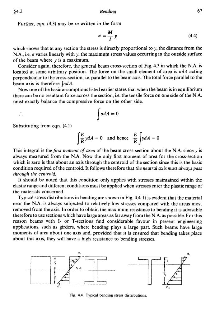
§4.2 Bending 67 Further,eqn.(4.3)may be re-written in the form M = (4.4) which shows that at any section the stress is directly proportional to y,the distance from the N.A.,i.e.a varies linearly with y,the maximum stress values occurring in the outside surface of the beam where y is a maximum. Consider again,therefore,the general beam cross-section of Fig.4.3 in which the N.A.is located at some arbitrary position.The force on the small element of area is odA acting perpendicular to the cross-section,i.e.parallel to the beam axis.The total force parallel to the beam axis is therefore JodA. Now one of the basic assumptions listed earlier states that when the beam is in equilibrium there can be no resultant force across the section,i.e.the tensile force on one side of the N.A. must exactly balance the compressive force on the other side odA=0 Substituting from eqn.(4.1) RYdA 0 and hence∫aA-0 This integral is the first moment of area of the beam cross-section about the N.A.since y is always measured from the N.A.Now the only first moment of area for the cross-section which is zero is that about an axis through the centroid of the section since this is the basic condition required of the centroid.It follows therefore that the neutral axis must always pass through the centroid. It should be noted that this condition only applies with stresses maintained within the elastic range and different conditions must be applied when stresses enter the plastic range of the materials concerned. Typical stress distributions in bending are shown in Fig.4.4.It is evident that the material near the N.A.is always subjected to relatively low stresses compared with the areas most removed from the axis.In order to obtain the maximum resistance to bending it is advisable therefore to use sections which have large areas as far away from the N.A.as possible.For this reason beams with I-or T-sections find considerable favour in present engineering applications,such as girders,where bending plays a large part.Such beams have large moments of area about one axis and,provided that it is ensured that bending takes place about this axis,they will have a high resistance to bending stresses. 1 士 Fig.4.4.Typical bending stress distributions
94.2 Bending 67 Further, eqn. (4.3) may be re-written in the form M I a=-y (4.4) which shows that at any section the stress is directly proportional to y, the distance from the N.A., i.e. a varies linearly with y, the maximum stress values occurring in the outside surface of the beam where y is a maximum. Consider again, therefore, the general beam cross-section of Fig. 4.3 in which the N.A. is located at some arbitrary position. The force on the small element of area is adA acting perpendicular to the cross-section, i.e. parallel to the beam axis. The total force parallel to the beam axis is therefore SadA. Now one of the basic assumptions listed earlier states that when the beam is in equilibrium there can be no resultant force across the section, i.e. the tensile force on one side of the N.A. must exactly balance the compressive force on the other side. adA = 0 s .. Substituting from eqn. (4.1) = 0 and hence E R IydA = 0 This integral is thefirst moment of area of the beam cross-section about the N.A. since y is always measured from the N.A. Now the only first moment of area for the cross-section which is zero is that about an axis through the centroid of the section since this is the basic condition required of the centroid. It follows therefore that rhe neutral axis must always pass through the centroid. It should be noted that this condition only applies with stresses maintained within the elastic range and different conditions must be applied when stresses enter the plastic range of the materials concerned. Typical stress distributions in bending are shown in Fig. 4.4. It is evident that the material near the N.A. is always subjected to relatively low stresses compared with the areas most removed from the axis. In order to obtain the maximum resistance to bending it is advisable therefore to use sections which have large areas as far away from the N.A. as possible. For this reason beams with I- or T-sections find considerable favour in present engineering applications, such as girders, where bending plays a large part. Such beams have large moments of area about one axis and, provided that it is ensured that bending takes place about this axis, they will have a high resistance to bending stresses. ut IT. Fig. 4.4. Typical bending stress distributions
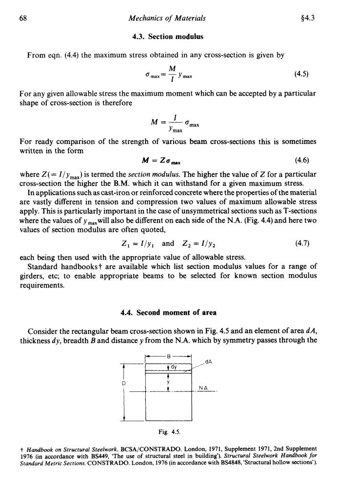
68 Mechanics of Materials §4.3 4.3.Section modulus From eqn.(4.4)the maximum stress obtained in any cross-section is given by M cmax=了ymax (4.5) For any given allowable stress the maximum moment which can be accepted by a particular shape of cross-section is therefore M-10mat ymax For ready comparison of the strength of various beam cross-sections this is sometimes written in the form M=ZG max (4.6) where Z(=I/ym)is termed the section modulus.The higher the value of Z for a particular cross-section the higher the B.M.which it can withstand for a given maximum stress. In applications such as cast-iron or reinforced concrete where the properties of the material are vastly different in tension and compression two values of maximum allowable stress apply.This is particularly important in the case of unsymmetrical sections such as T-sections where the values of ymxwill also be different on each side of the N.A.(Fig.4.4)and here two values of section modulus are often quoted, Z1=I/y and Z2=I/y2 (4.7) each being then used with the appropriate value of allowable stress. Standard handbookst are available which list section modulus values for a range of girders,etc;to enable appropriate beams to be selected for known section modulus requirements. 4.4.Second moment of area Consider the rectangular beam cross-section shown in Fig.4.5 and an element of area dA, thickness dy,breadth B and distance y from the N.A.which by symmetry passes through the dA dy D NA Fig.4.5. t Handbook on Structural Steelwork.BCSA/CONSTRADO.London,1971,Supplement 1971,2nd Supplement 1976 (in accordance with BS449,The use of structural steel in building').Structural Steelwork Handbook for Standard Metric Sections.CONSTRADO.London,1976 (in accordance with BS4848,'Structural hollow sections')
68 Mechanics of Materials $4.3 4.3. Section modulus From eqn. (4.4) the maximum stress obtained in any cross-section is given by M I omax= -Ymax (4.5) For any given allowable stress the maximum moment which can be accepted by a particular shape of cross-section is therefore M=- I Ymax For ready comparison of the strength of various beam cross-sections this is sometimes written in the form OmaX M = Za, (4.6) where Z( = I/ymax) is termed the section modulus. The higher the value of Z for a particular cross-section the higher the B.M. which it can withstand for a given maximum stress. In applications such as cast-iron or reinforced concrete where the properties of the material are vastly different in tension and compression two values of maximum allowable stress apply. This is particularly important in the case of unsymmetrical sections such as T-sections where the values of ymaxwi1l also be different on each side of the N.A. (Fig. 4.4) and here two values of section modulus are often quoted, Z, = I/y, and Z, =Ily, (4.7) each being then used with the appropriate value of allowable stress. Standard handbooks t are available which list section modulus values for a range of girders, etc; to enable appropriate beams to be selected for known section modulus requirements. 4.4. Second moment of area Consider the rectangular beam cross-section shown in Fig. 4.5 and an element of area dA, thickness dy, breadth B and distance y from the N.A. which by symmetry passes through the Fig. 4.5. t Handbook on Structural Steelwork. BCSA/CONSTRADO. London, 1971, Supplement 1971, 2nd Supplement 1976 (in accordance with BS449, ‘The use of structural steel in building’). Structural Steelwork Handbook for Standard Metric Sections. CONSTRADO. London, 1976 (in accordance with BS4848, ‘Structural hollow sections’)
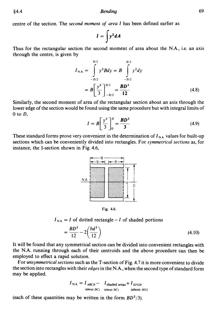
§4.4 Bending 69 centre of the section.The second moment of area I has been defined earlier as dA Thus for the rectangular section the second moment of area about the N.A.,i.e.an axis through the centre,is given by D/2 D/2 INA= y2Bdy=B y'dy -D/2 -D/2 y372 BD3 =83o212 (4.8) Similarly,the second moment of area of the rectangular section about an axis through the lower edge of the section would be found using the same procedure but with integral limits of 0 to D, (4.9) These standard forms prove very convenient in the determination of INA values for built-up sections which can be conveniently divided into rectangles.For symmetrical sections as,for instance,the I-section shown in Fig.4.6, 0- NA Fig.4.6. INA =I of dotted rectangle-I of shaded portions BD3 12-12 (4.10) It will be found that any symmetrical section can be divided into convenient rectangles with the N.A.running through each of their centroids and the above procedure can then be employed to effect a rapid solution. For unsymmetrical sections such as the T-section of Fig.4.7 it is more convenient to divide the section into rectangles with their edges in the N.A.,when the second type of standard form may be applied. INA.=I ABCD-I shaded areas+I EFGH (about DC)(about DC)(about HG) (each of these quantities may be written in the form BD3/3)
84.4 Bending 69 centre of the section. The second moment of area I has been defined earlier as I= yZdA Thus for the rectangular section the second moment of area about the N.A., i.e. an axis through the centre, is given by I 012 Di2 - DJ2 -D/2 = B[$]yl,, = rz BD3 Similarly, the second moment of area of the rectangular section about an axis through the lower edge of the section would be found using the same procedure but with integral limits of 0 to D. These standard forms prove very convenient in the determination of I N.A. values for built-up sections which can be conveniently divided into rectangles. For symmetrical sections as, for instance, the I-section shown in Fig. 4.6, Fig. 4.6. 1N.A. = I of dotted rectangle - I of shaded portions BD3 12 (4.10) It will be found that any symmetrical section can be divided into convenient rectangles with the N.A. running through each of their centroids and the above procedure can then be employed to effect a rapid solution. For unsymmetrical sections such as the T-section of Fig. 4.7 it is more convenient to divide the section into rectangles with their edges in the N.A., when the second type of standard form may be applied. IN.A = IABCD- Ishaded areas+ IEFGH (abut DC) (abut K) (about HC) (each of these quantities may be written in the form BD3/3)
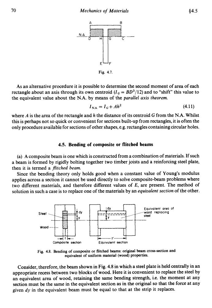
70 Mechanics of Materials §4.5 NA Fig.4.7. As an alternative procedure it is possible to determine the second moment of area of each rectangle about an axis through its own centroid (I=BD3/12)and to"shift"this value to the equivalent value about the N.A.by means of the parallel axis theorem. INA=IG+Ah2 (4.11) where A is the area of the rectangle and h the distance of its centroid G from the N.A.Whilst this is perhaps not so quick or convenient for sections built-up from rectangles,it is often the only procedure available for sections of other shapes,e.g.rectangles containing circular holes. 4.5.Bending of composite or flitched beams (a)A composite beam is one which is constructed from a combination of materials.If such a beam is formed by rigidly bolting together two timber joists and a reinforcing steel plate, then it is termed a flitched beam. Since the bending theory only holds good when a constant value of Young's modulus applies across a section it cannot be used directly to solve composite-beam problems where two different materials,and therefore different values of E,are present.The method of solution in such a case is to replace one of the materials by an equivalent section of the other. Equivalent areo of Steel wood replocing steel Wood Composite section Equivolent section Fig.4.8.Bending of composite or flitched beams:original beam cross-section and equivalent of uniform material (wood)properties. Consider,therefore,the beam shown in Fig.4.8 in which a steel plate is held centrally in an appropriate recess between two blocks of wood.Here it is convenient to replace the steel by an equivalent area of wood,retaining the same bending strength,i.e.the moment at any section must be the same in the equivalent section as in the original so that the force at any given dy in the equivalent beam must be equal to that at the strip it replaces
70 Mechanics of Materials $4.5 EF U Fig. 4.1. As an alternative procedure it is possible to determine the second moment of area of each rectangle about an axis through its own centroid (I, = 8D3/12) and to “shift” this value to the equivalent value about the N.A. by means of the parallel axis theorem. IN.A. = IG+ Ah2 where A is the area of the rectangle and h the distance of its centroid G from the N.A. Whilst this is perhaps not so quick or convenient for sections built-up from rectangles, it is often the only procedure available for sections of other shapes, e.g. rectangles containing circular holes. (4.1 1) 4.5. Bending of composite or flitcbed beams (a) A composite beam is one which is constructed from a combination of materials. If such a beam is hrmed by rigidly bolting together two timber joists and a reinforcing steel plate, then it is termed a Pitched beam. Since the bending theory only holds good when a constant value of Young’s modulus applies across a section it cannot be used directly to solve composite-beam problems where two different materials, and therefore different values of E, are present. The method of solution in such a case is to replace one of the materials by an equivalent section of the other. Steel Wood Equivalent ore0 of wood repiocing steel Composite section Equivuient section Fig. 4.8. Bending of composite or flitched beams: original beam cross-section and equivalent of uniform material (wood) properties. Consider, therefore, the beam shown in Fig. 4.8 in which a steel plate is held centrally in an appropriate recess between two blocks of wood. Here it is convenient to replace the steel by an equivalent area of wood, retaining the same bending strength, i.e. the moment at any section must be the same in the equivalent section as in the original so that the force at any given dy in the equivalent beam must be equal to that at the strip it replaces
§4.6 Bending 71 otdy o't'dy ot a't' (4.12) &Et =&'E't' since a=E Again,for true similarity the strains must be equal, 8=8 t'E Et =E't'or (4.13) t E' i.e. t-Et (4.14) Thus to replace the steel strip by an equivalent wooden strip the thickness must be multiplied by the modular ratio E/E'. The equivalent section is then one of the same material throughout and the simple bending theory applies.The stress in the wooden part of the original beam is found directly and that in the steel found from the value at the same point in the equivalent material as follows: ot' from eqn.(4.12) σE and from egn.(4.13) -E or a- (4.15) i.e. stress in steel modular ratio x stress in equivalent wood The above procedure,of course,is not limited to the two materials treated above but applies equally well for any material combination.The wood and steel flitched beam was merely chosen as a convenient example. 4.6.Reinforced concrete beams-simple tension reinforcement Concrete has a high compressive strength but is very weak in tension.Therefore in applications where tension is likely to result,e.g.bending,it is necessary to reinforce the concrete by the insertion of steel rods.The section of Fig.4.9a is thus a compound beam and can be treated by reducing it to the equivalent concrete section,shown in Fig.4.9b. In calculations,the concrete is assumed to carry no tensile load;hence the gap below the N.A.in Fig.4.9b.The N.A.is then fixed since it must pass through the centroid of the area assumed in this figure:i.e.moments of area about the N.A.must be zero. Let t=tensile stress in the steel, c compressive stress in the concrete, A total area of steel reinforcement, m=modular ratio,Esteel/Econcrete other symbols representing the dimensions shown in Fig.4.9
54.6 Bending .. since atdy = a’t’dy at = a’t’ &Et = &‘Et’ a -=E & Again, for true similarity the strains must be equal, .. E = E’ i.e. E E t‘=-t 71 (4.12) (4.13) (4.14) Thus to replace the steel strip by an equivalent wooden strip the thickness must be multiplied by the modular ratio EIE. The equivalent section is then one of the same material throughout and the simple bending theory applies. The stress in the wooden part of the original beam is found directly and that in the steel found from the value at the same point in the equivalent material as follows: a t’ a’ t from eqn. (4.12) - - -- and from eqn. (4.13) aE E a‘ E E --- - or a=--6‘ (4.15) i.e. stress in steel = modular ratio x stress in equivalent wood The above procedure, of course, is not limited to the two materials treated above but applies equally well for any material combination. The wood and steel flitched beam was merely chosen as a convenient example. 4.6. Reinforced concrete beams - simple tension reinforcement Concrete has a high compressive strength but is very weak in tension. Therefore in applications where tension is likely to result, e.g. bending, it is necessary to reinforce the concrete by the insertion of steel rods. The section of Fig.’4.9a is thus a compound beam and can be treated by reducing it to the equivalent concrete section, shown in Fig. 4.9b. In calculations, the concrete is assumed to carry no tensile load; hence the gap below the N.A. in Fig. 4.9b. The N.A. is then fixed since it must pass through the centroid of the area assumed in this figure: i.e. moments of area about the N.A. must be zero. Let t = tensile stress in the steel, c = compressive stress in the concrete, A = total area of steel reinforcement, rn = modular ratio, Esteel/Econcrete, other symbols representing the dimensions shown in Fig. 4.9