2018/3/11 圆上活大学 Overview of Lectures 国上清大学 0.Overview 14/15 Performance(a,b) 1.Introduction 16.Aircraft certification 2.Overall configuration (a,b) 17 Aviation economics 3.Preliminary weight estimation 18.Svstem integration and Aircraft Design 4.Refined weight estimation confiquration management 5.Fuselage design (飞行器设计) 6.Aerodynamic design(a,b) 9.Thrust/Weight ratio and wing loading0.Military aircraft design- 10.Landing gear and Aircraft systems overview 21.Environmental issues 11.Power plant Wenbin Song 12.Stability and control 22.Design skills School of Aeronautics and Astronautics 13.Loads,materials and structures oorornenin ong Content 国上活美大坐 International Standard Atmosphere (ISA) 圆上清道大坐 Aerodynamic Design (2) An atmospheric model of how pressure,density,temperature,and Airfoil viscosity relate to altitudes (ISO 2533:1975) -Wing ·Basic law -Fuselage -Tail Ge etry Buoyancy Equation Aerodynamic Forces and Moments (2) ·Troposphere -Lift Estimation -Drag Estimation -Moment Estimation (not included Stratosphere (Temperature Constant,about 10-50km) CFD-based aerodynamic shape design (2) netry Param terization 2=e 卫-★ -CFD Sim lation % Reverse Design and Numerical Optimization Sea-level data 4-1SC五-23.150A-1225k1we-340294eh&-0665R-270527J-g.k 3 oerandenn ong 4 ISA Data Chart 国上洋大坐 Topics Covered 园上海发大坐 1.000 ·t Clean configuration -Effect of high lift devices on aero coefficients 0.80 ·Dag a70 -Drag breakdown-according to physical mechanisms form drag friction drag wave drag 0.500 Drag breakdown-component based 0500 ·Use of form factors Trim drag 0.400 ·Methods and software 0.3000 DATCOM,ESDU 02800 -Coding it yourselr 0.000 0 5000 10000 15000 30a0 Shanghal Jlao Tong Universty-Dr.Wenbin Song rslty-Dr.V(enbin Song 1
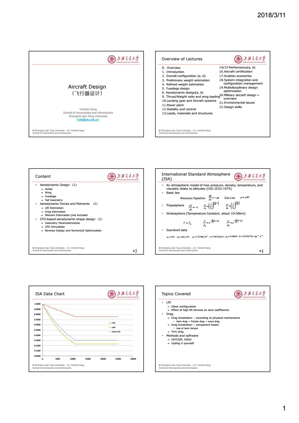
2018/3/11 1 © Shanghai Jiao Tong University – Dr. Wenbin Song School of Aeronautics and Astronautics Wenbin Song School of Aeronautics and Astronautics Shanghai Jiao Tong University swb@sjtu.edu.cn Aircraft Design (飞行器设计) © Shanghai Jiao Tong University – Dr. Wenbin Song School of Aeronautics and Astronautics Overview of Lectures 0. Overview 1. Introduction 2. Overall configuration (a, b) 3. Preliminary weight estimation 4. Refined weight estimation 5. Fuselage design 6. Aerodynamic design(a, b) 9. Thrust/Weight ratio and wing loading 10.Landing gear and Aircraft systems 11.Power plant 12.Stability and control 13.Loads, materials and structures 14/15 Performance(a, b) 16.Aircraft certification 17.Aviation economics 18.System integration and configuration management 19.Multidisciplinary design optimization 20.Military aircraft design – overview 21.Environmental issues 22.Design skills © Shanghai Jiao Tong University – Dr. Wenbin Song School of Aeronautics and Astronautics Content • Aerodynamic Design (2) – Airfoil – Wing – Fuselage – Tail Geometry • Aerodynamic Forces and Moments (2) – Lift Estimation – Drag Estimation – Moment Estimation (not included • CFD-based aerodynamic shape design (2) – Geometry Parameterization – CFD Simulation – Reverse Design and Numerical Optimization •3 © Shanghai Jiao Tong University – Dr. Wenbin Song School of Aeronautics and Astronautics International Standard Atmosphere (ISA) • An atmospheric model of how pressure, density, temperature, and viscosity relate to altitudes (ISO 2533:1975) • Basic law • Troposphere • Stratosphere (Temperature Constant, about 10-50km) • Sea-level data •4 g dz dp Buoyancy Equation Gas Law p RT L dz dT 1 0 0 RL g T T RL g T T p p 0 0 0 0 z z RT g e 0 0 z z RT g e p p T T0 t0 15C T0 288.15C 3 0 1.225kg / m a 340.294m/s g0 9.80665 1 1 287.05278 R J kg K © Shanghai Jiao Tong University – Dr. Wenbin Song School of Aeronautics and Astronautics ISA Data Chart 0.0000 0.1000 0.2000 0.3000 0.4000 0.5000 0.6000 0.7000 0.8000 0.9000 1.0000 0 5000 10000 15000 20000 25000 30000 T/T0 p/p0 density ratio © Shanghai Jiao Tong University – Dr. Wenbin Song School of Aeronautics and Astronautics Topics Covered • Lift – Clean configuration – Effect of high lift devices on aero coefficients • Drag – Drag breakdown – according to physical mechanisms • form drag + friction drag + wave drag – Drag breakdown – component based • Use of form factors – Trim drag • Methods and software – DATCOM, ESDU – Coding it yourself
2018/3/11 Origins of Aerodynamic Forces 图上活大学 Factors that influence aerodynamic forces 国上清大学 Shear forces->skin friction drag Geometry Pressure difference.>lift,pressure drag Surface roughness Supersonic flight->wave drag ·Flight speed Altitude(air density,temperature,pressure) 。Reynolds Number(Re) SHEAR MOLECULES Wind tunnel -CFD (numerical wing tunnel) O是ZTw保s.OUTWARDO oorn enin Song 圆上清文大些 Lift 圆上洋文廷大蜂 Lift-Aerodynamic force perpendicular to the flow direction 地m业c.G-(侷) CL-essentially linear before reaching the stall angle For setting the wing incidence angle Section B-1 For calculatingdrag-due-to lift AERODYNAMIC FORCES-LIFT -For longitudinalstability analysis For cruise condition,the lift requirement can be calculated from CL=L/q Srer =W/gSrer nwentin ong Effect of Camber and AR on CLa 圈上洋文通大坐 Subsonic Lift-Curve Slope 园上海发大坐 2元A EFFECT OF CAMBER EFFECT OF ASPECT RATIO CLa=- 2+ B ASPECT RATIO 4+ l+tan2 3 B2 where B2=1-M2 7= C 2π/ airfoil efficiency (o.95) fuselage lift factor F=min(1.071+d/b)2,0.98) Wing effective aspect ratio Aegecme =4(1+1.9h/b)Endplate due to wing tip modifications Aee≈l.2 Winglet A is the geometric aspect ratio of the complete reference wing ry-ur.wwennn song 2
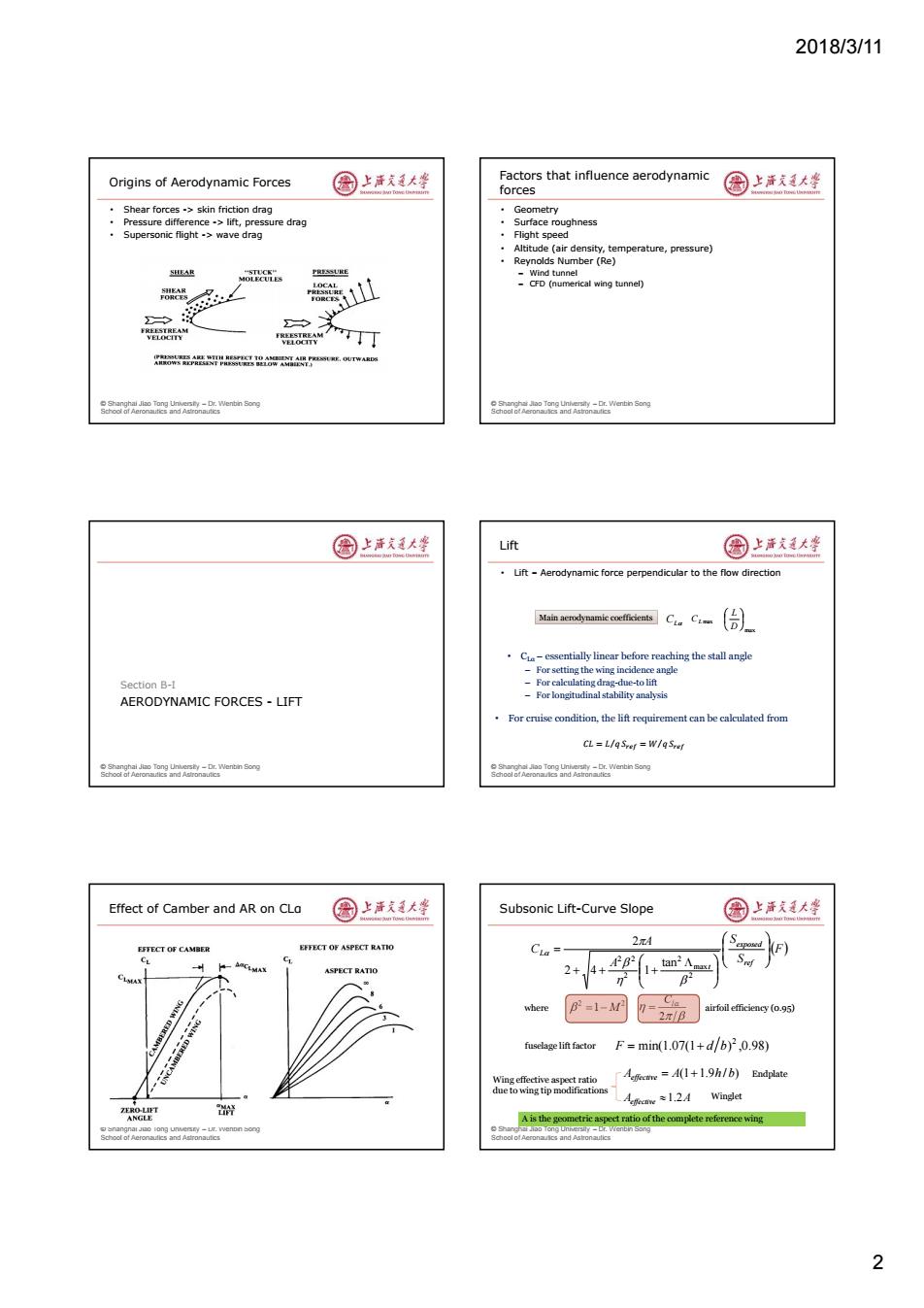
2018/3/11 2 © Shanghai Jiao Tong University – Dr. Wenbin Song School of Aeronautics and Astronautics Origins of Aerodynamic Forces • Shear forces -> skin friction drag • Pressure difference -> lift, pressure drag • Supersonic flight -> wave drag © Shanghai Jiao Tong University – Dr. Wenbin Song School of Aeronautics and Astronautics Factors that influence aerodynamic forces • Geometry • Surface roughness • Flight speed • Altitude (air density, temperature, pressure) • Reynolds Number (Re) – Wind tunnel – CFD (numerical wing tunnel) © Shanghai Jiao Tong University – Dr. Wenbin Song School of Aeronautics and Astronautics AERODYNAMIC FORCES - LIFT Section B-I © Shanghai Jiao Tong University – Dr. Wenbin Song School of Aeronautics and Astronautics Lift • Lift – Aerodynamic force perpendicular to the flow direction CL Main aerodynamic coefficients CL max max D L • CLα – essentially linear before reaching the stall angle – For setting the wing incidence angle – For calculating drag-due-to lift – For longitudinal stability analysis 𝐶𝐿 = 𝐿 𝑞⁄ 𝑆 = 𝑊 𝑞⁄ 𝑆 • For cruise condition, the lift requirement can be calculated from © Shanghai Jiao Tong University – Dr. Wenbin Song School of Aeronautics and Astronautics Effect of Camber and AR on CLα © Shanghai Jiao Tong University – Dr. Wenbin Song School of Aeronautics and Astronautics Subsonic Lift-Curve Slope F S S A A C ref exposed t L 2 max 2 2 2 2 tan 2 4 1 2 2 2 1 M 2 Cl where airfoil efficiency (0.95) fuselage lift factor min(1.07(1 ) ,0.98) 2 F d b A A(1 1.9h / b) effective Aeffective 1.2A Endplate Winglet Wing effective aspect ratio due to wing tip modifications A is the geometric aspect ratio of the complete reference wing
2018/3/11 Supersonic Lift-Curve Slope 国上唐美大坐 Transonic Lift-Curve Slope 国上清大学 ·For“pure”supersonic wings(Mo>l) 8a2提 THEDRO TICAL La=41B 5,"m- where,B=M-1 M>1/COsALE Curve fitting is SICI AL BCT RATIO WIMA often used for the a =aresin(1/M) cases oftransonic flight regime OW ASPECT RAT For real,nontrapezoidal wing planforms, approximate charts and panel methods are usually used (Raymer,pp.314-315) 15 5 Erfect of Ma,Sweep()on CLmax()圈上活支道大坐 Effect of Leading Edge Radius on CLmax 园上活道大整 For subsonic wing (Ma<0.8) CLmas=0.9C1mxco个025 Low aspect ratio High aspect ratio 3 4 C.+lcosA 16 45C.+IXcOsAu) -o C-CAC. Use of leading edge sharpness _C+a+小e parameters Ay to characterize eratsad Shaded items are defined using a number ofcharts in Chapter 12.pp317-321. Design of High-Lift Devices 国上洋大坐 Lift in Summary 园上海发大坐 Use of lift coefficients in the aerodynamic design process Setting wing incidence angle C Caleulation of drag-due-to-lift Analysis of longitudinal stability CLma Takeoff weight △CLm=0.9AC D Range Aau=(△au) slty-Dr.V(enbin Song 3
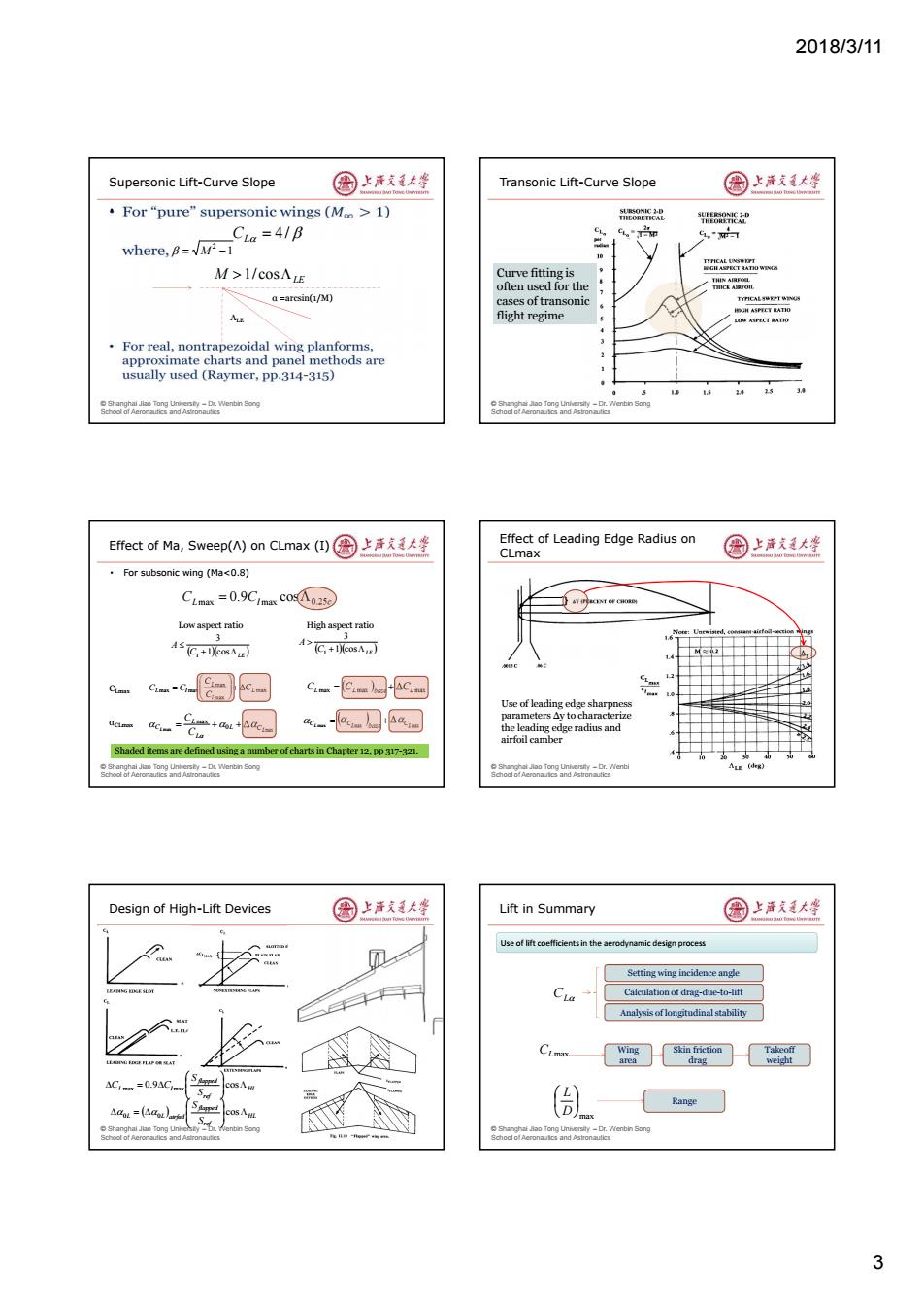
2018/3/11 3 © Shanghai Jiao Tong University – Dr. Wenbin Song School of Aeronautics and Astronautics Supersonic Lift-Curve Slope • CL 4 / 1 2 M α =arcsin(1/M) ΛLE M LE 1/ cos © Shanghai Jiao Tong University – Dr. Wenbin Song School of Aeronautics and Astronautics Transonic Lift-Curve Slope Curve fitting is often used for the cases of transonic flight regime © Shanghai Jiao Tong University – Dr. Wenbin Song School of Aeronautics and Astronautics Effect of Ma, Sweep(Λ) on CLmax (I) • For subsonic wing (Ma<0.8) CLmax Cl max 0.25c 0.9 cos C LE A 1 cos 3 1 C LE A 1 cos 3 1 Low aspect ratio High aspect ratio CLmax αCLmax max max max max max L l L L l C C C C C max max 0 max L L CL L L C C C CLmax CLmax base CLmax CL max CL max base CLmax Shaded items are defined using a number of charts in Chapter 12, pp 317-321. © Shanghai Jiao Tong University – Dr. Wenbin Song School of Aeronautics and Astronautics Effect of Leading Edge Radius on CLmax Use of leading edge sharpness parameters Δy to characterize the leading edge radius and airfoil camber © Shanghai Jiao Tong University – Dr. Wenbin Song School of Aeronautics and Astronautics Design of High-Lift Devices HL ref flapped L l S S C C 0.9 cos max max HL ref flapped L L airfoil S S cos 0 0 © Shanghai Jiao Tong University – Dr. Wenbin Song School of Aeronautics and Astronautics Lift in Summary CL CLmax max D L Wing area Skin friction drag Takeoff weight Range Setting wing incidence angle Calculation of drag-due-to-lift Analysis of longitudinal stability Use of lift coefficients in the aerodynamic design process
2018/3/11 圆上活大学 Drag Terminology 国上清大学 Drag- Profile Drag +Induced Drag!+Wave Drag 恤rg然am SECTION B-II AERODYNAMIC FORCES-DRAG oorornenin ong zero lift drag Drag Terminology-中文版 国上活大坐 Total Drag Decomposition 圆上洋廷大整 Fratve dag 日过 Zero-lift,or parasite drag- 即力二 型用 +诱导阻力 +激波阻力 农 1 Induced drag,or drag due to lift- Cni=kC2=CLπeA Drag due to compressibility,or wave drag for transonic flows, therefore Cpo=Cpoform +Cpofriction+Cpi 升致阳力 nbin Song零升阴力 oerandenn ong 22 More Details on Induced Drag 国上洋大坐 Parasite Drag 国上洋大学 with induced Cp.i-Cp.Cp. CoC Second approach uses"Component Buildup Method" CccCr Shanghal Jao Tong Universty-Dr.Wenbin Soog erslty-Dr.Wrenbin Song 4
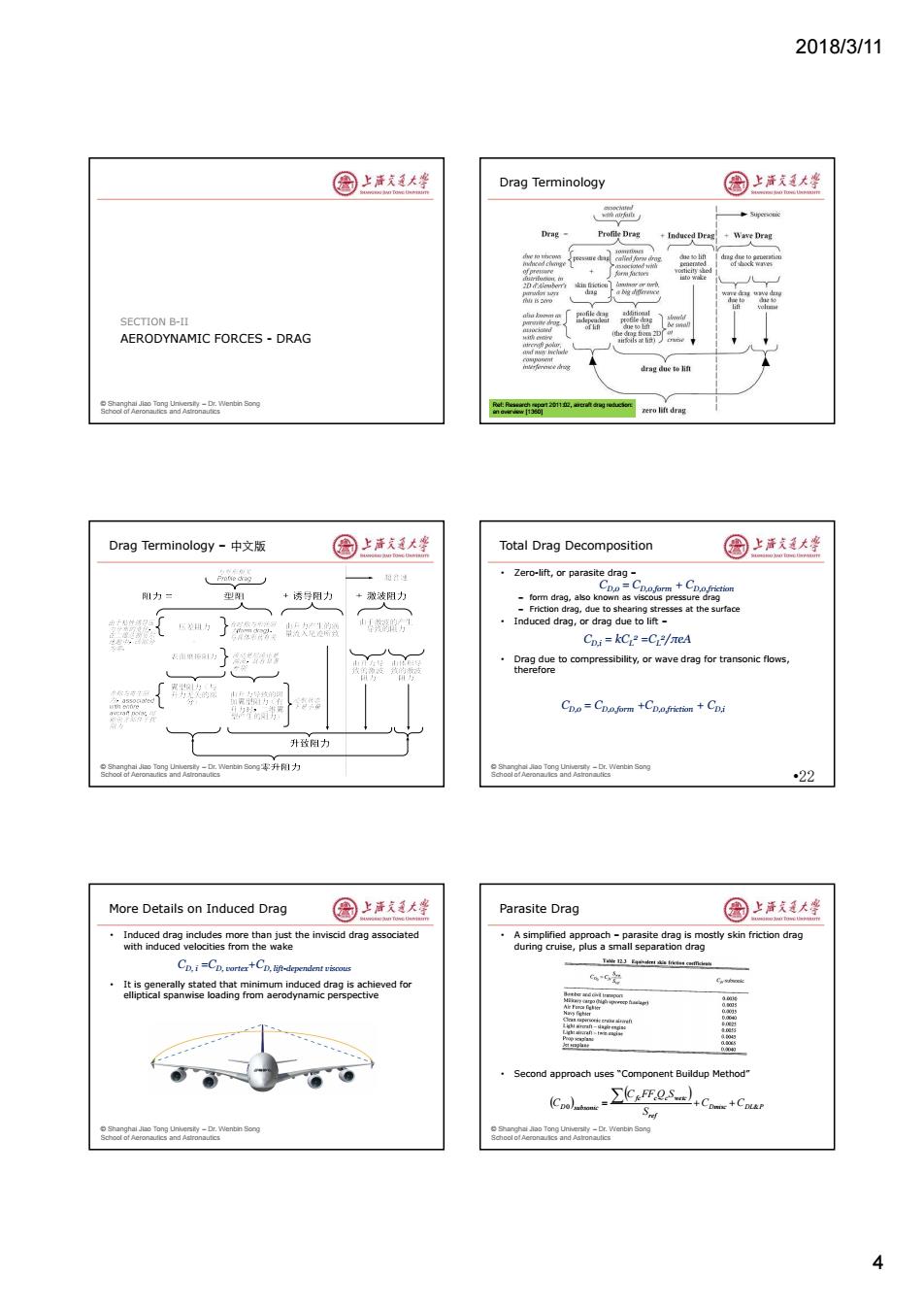
2018/3/11 4 © Shanghai Jiao Tong University – Dr. Wenbin Song School of Aeronautics and Astronautics AERODYNAMIC FORCES - DRAG SECTION B-II © Shanghai Jiao Tong University – Dr. Wenbin Song School of Aeronautics and Astronautics Drag Terminology Ref: Research report 2011:02, aircraft drag reduction: an overview [1360] © Shanghai Jiao Tong University – Dr. Wenbin Song School of Aeronautics and Astronautics Drag Terminology – 中文版 © Shanghai Jiao Tong University – Dr. Wenbin Song School of Aeronautics and Astronautics Total Drag Decomposition • Zero-lift, or parasite drag – – form drag, also known as viscous pressure drag – Friction drag, due to shearing stresses at the surface • Induced drag, or drag due to lift – • Drag due to compressibility, or wave drag for transonic flows, therefore •22 CD,0 = CD,0,form + CD,0,friction CD,i = kCL 2 =CL 2 /πeA CD,0 = CD,0,form +CD,0,friction + CD,i © Shanghai Jiao Tong University – Dr. Wenbin Song School of Aeronautics and Astronautics More Details on Induced Drag • Induced drag includes more than just the inviscid drag associated with induced velocities from the wake • It is generally stated that minimum induced drag is achieved for elliptical spanwise loading from aerodynamic perspective CD, i =CD, vortex+CD, lift-dependent viscous © Shanghai Jiao Tong University – Dr. Wenbin Song School of Aeronautics and Astronautics Parasite Drag • A simplified approach – parasite drag is mostly skin friction drag during cruise, plus a small separation drag • Second approach uses “Component Buildup Method” Dmisc DL P ref fc c c wetc D subsonic C C S C FF Q S C 0 &
2018/3/11 Skin Friction Drag:Laminar flow Laminar,Transitional,and Turbulent over a smooth flat plate 图上清大华 Flow 圈上清文大华 laminar transitional turbulent X=0 X=1 9=0.064.06 10 Turbulent Local skin friction 1 Re, coefficient -0.74Rex6 1000C4 Average,or C= 1.328 Transitional friction coefficient Rer Laminar C=1.328Rex12 Re=pV1/u where,is characteristic length,fuselage length 1 or winglean aerodynamic chord 104 105 106 107 Rex ong 26 Skin Friction Drag in Turbulent Flow 国上活大蜂 Wave Drag 国上活支大峰 Drag increases due to compressibility effects for airspeeds higher DI=CFASq 0.0045 than critical Mach number Mcr,due to the appearance of shock waves. ·This increase has a moderate slope 05 until reachina Cris small but the 0.0035 drag divergence dynamic pressure and Mach Mdd wetted area are large ·Drag diverge Mach is defined 0.0025 02 as 70- 106107 nt ge or 0.455 CFhrb (l0gR)s1+0.144M2p65 106<Re<109 Fig.8 Wave drag inerease at transonie airxpeeds. M。 Drag Build-up for the Wing 国上清大学 Drag build-Up with Component Form Factors 园上清天大学 Dw.o=Dwr+Dw.p zero-lift drag CD.or= wg Sq Dwo=CEnurbswet q+k CEnurbswet q Cooe -KyCrah SeZer- coefficient for the wing Dwo=(1+k)CEnirbSwet q Dw.o=KwCrsuet q CD.o= KC S Zero-lift drag The drag estimate is based on a multiple of the friction drag.K,the coefficient for the form factor for the wing -1 airplane erslty-Dr.V(enbin Song 5
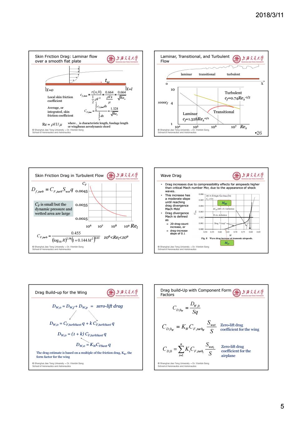
2018/3/11 5 © Shanghai Jiao Tong University – Dr. Wenbin Song School of Aeronautics and Astronautics Skin Friction Drag: Laminar flow over a smooth flat plate tw , 2 , 0 0.664 0.664 1 Re 2 f lam x x c Vx V , 0 , 0 1.328 Re l f lam F lam l l c dx C dx Local skin friction coefficient Average, or integrated, skin friction coefficient X=0 X=l Re Vl / where , is characteristic length, fuselage length or wing mean aerodynamic chord l © Shanghai Jiao Tong University – Dr. Wenbin Song School of Aeronautics and Astronautics Laminar, Transitional, and Turbulent Flow •26 laminar transitional turbulent 104 105 106 107 Rex 10 4 1 1000cf Turbulent cf=0.74Rex -1/5 Laminar cf=1.328Rex -1/2 Transitional 0 X © Shanghai Jiao Tong University – Dr. Wenbin Song School of Aeronautics and Astronautics Skin Friction Drag in Turbulent Flow D C S q f turb F turb wet , , 106<Rel<109 CF is small but the dynamic pressure and wetted area are large 0.65 2.58 2 10 , log 1 0.144 0.455 R M CF turb 106 107 108 109 Rel 0.0045 0.0035 0.0025 CF © Shanghai Jiao Tong University – Dr. Wenbin Song School of Aeronautics and Astronautics Wave Drag • Drag increases due to compressibility effects for airspeeds higher than critical Mach number Mcr, due to the appearance of shock waves. • This increase has a moderate slope until reaching drag divergence Mach Mdd • Drag divergence Mach is defined as – 20-drag-count increase, or – drag-increase slope of 0.1 Mcr Mdd © Shanghai Jiao Tong University – Dr. Wenbin Song School of Aeronautics and Astronautics Drag Build-up for the Wing DW,0 = DW,f + DW,p = zero-lift drag DW,0 = CF,turbSwet q + k CF,turbSwet q DW,0 = (1 + k) CF,turbSwet q DW,0 = KWCFSwet q The drag estimate is based on a multiple of the friction drag, KW, the form factor for the wing © Shanghai Jiao Tong University – Dr. Wenbin Song School of Aeronautics and Astronautics Drag build-Up with Component Form Factors ,0 ,0W W D D C Sq ,0 , W W wet D W F turb S C K C S ,0 , 1 i i n wet D i F turb i S C K C S Zero-lift drag coefficient for the wing Zero-lift drag coefficient for the airplane