2018/3/11 圆上活大学 Overview of Lectures 国上清大学 0.Overview 14/15 Performance(a,b) 1.Introduction 16.Aircraft certification 2.Overall configuration(a,b) 17 Aviation economics 3.Preliminary weight estimation 18.Svstem integration and Aircraft Design 4.Refined weight estimation confiquration management 5.Fuselage design (飞行器设计) 6/7/8.Aerodynamic design(a,b,c) 9.Thrust/Weight ratio and wing loading 20.Military aircraft design- 10.Landing gea r and Aircraft systems overview 21.Environmental issues 11.Power plant Wenbin Song 22.Design skills 12Stability and control School of Aeronautics and Astronautics Shangy 13.Loads,materials and structures o r nd 0171 Content 国上清支道大坐 圆上洋文廷大蜂 Aerodynamic Design-configuration and component (2) ration alre小covered -Airfoil Wing -Fuselage(covered in fuselage design) -Tail Geo -Lift Estimation -Drag Estimation CFD-based aerodynamic shape design-physics-based numerical Aerodynamic Design-configuration and component modeling (2) etry Para meterization CFD Sim inverse Design and Numerical Optimization eagaea2-w58 8oa6o0e四k-a88 Tasks in Aerodynamic Design 园上洋文通大学 Mach number 圆上洋文大华 ·Design of aircraft configurations and geometry Ma=0.85 Provide load data for Ma=0.5 detailed structural design 。 Aeroelastic analysis Ma=7-10 ethods Mach number increases Ma=0.78 Ma=2.0 1
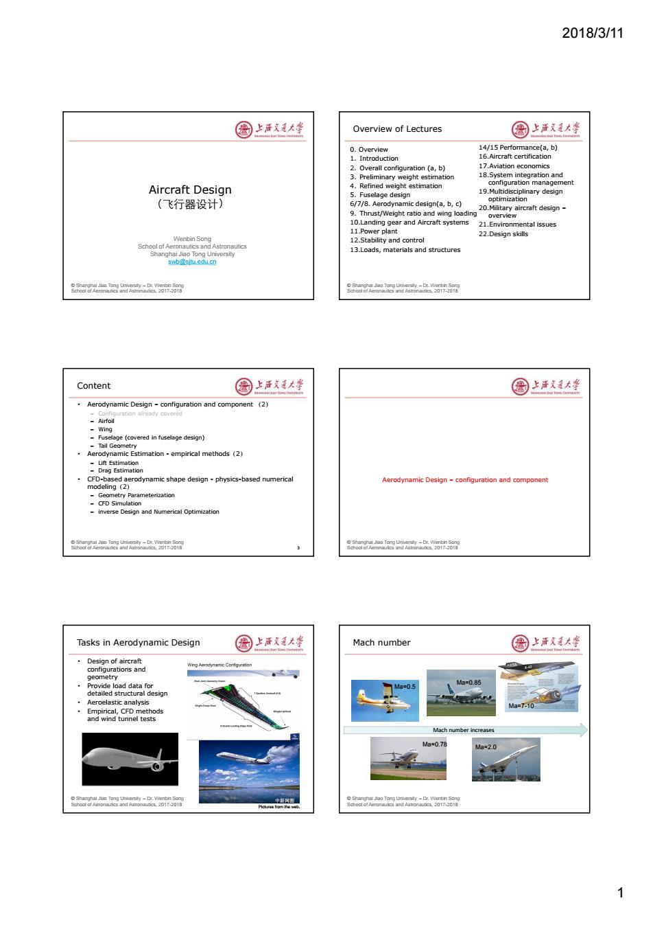
2018/3/11 1 © Shanghai Jiao Tong University – Dr. Wenbin Song School of Aeronautics and Astronautics, 2017-2018 Wenbin Song School of Aeronautics and Astronautics Shanghai Jiao Tong University swb@sjtu.edu.cn Aircraft Design (飞行器设计) © Shanghai Jiao Tong University – Dr. Wenbin Song School of Aeronautics and Astronautics, 2017-2018 Overview of Lectures 0. Overview 1. Introduction 2. Overall configuration (a, b) 3. Preliminary weight estimation 4. Refined weight estimation 5. Fuselage design 6/7/8. Aerodynamic design(a, b, c) 9. Thrust/Weight ratio and wing loading 10.Landing gear and Aircraft systems 11.Power plant 12.Stability and control 13.Loads, materials and structures 14/15 Performance(a, b) 16.Aircraft certification 17.Aviation economics 18.System integration and configuration management 19.Multidisciplinary design optimization 20.Military aircraft design – overview 21.Environmental issues 22.Design skills © Shanghai Jiao Tong University – Dr. Wenbin Song School of Aeronautics and Astronautics, 2017-2018 Content • Aerodynamic Design – configuration and component (2) – Configuration already covered – Airfoil – Wing – Fuselage (covered in fuselage design) – Tail Geometry • Aerodynamic Estimation - empirical methods(2) – Lift Estimation – Drag Estimation • CFD-based aerodynamic shape design - physics-based numerical modeling(2) – Geometry Parameterization – CFD Simulation – inverse Design and Numerical Optimization 3 © Shanghai Jiao Tong University – Dr. Wenbin Song School of Aeronautics and Astronautics, 2017-2018 Aerodynamic Design – configuration and component © Shanghai Jiao Tong University – Dr. Wenbin Song School of Aeronautics and Astronautics, 2017-2018 Tasks in Aerodynamic Design • Design of aircraft configurations and geometry • Provide load data for detailed structural design • Aeroelastic analysis • Empirical, CFD methods and wind tunnel tests Pictures from the web. © Shanghai Jiao Tong University – Dr. Wenbin Song School of Aeronautics and Astronautics, 2017-2018 Mach number Mach number increases Ma=2.0 Ma=0.5 Ma=0.78 Ma=7-10 Ma=0.85
2018/3/11 Wing Aerodynamics 国上活大坐 Wing design requirements 国上清大学 Speed range:low speed,transonic,supersonic,and hypersonic Wing areas Wing planform and airfoils 0P9326 M:77 ichool of Aeronaulies and,2017-2018 Design features of modern transport aircraft 圈上活大坐 Key technologies for wing design 圆上洋支廷大整 Advanced Supercritical Airfoil Design -Leading edge optimization in combination with droop nose design -Optimized rear-loading design -More robust (less sensitive to flow conditions,etc) 处构重量竖(与图力最小手婚) 足铁的边蒂空用(与气动录计要表平丽) Planform optimization 坦航速度的提高(0.82-0.85)雷是优化拉术的应用 -Wing root modification 一灵先进的第型(开里比。煮流/边暴基干找,后缘) Wingtip design (blending winglet,raked winglet,folding winglet) ·3 D wing design -Wina/Enaine interference 动空制技木 -point design Morphing wing 复材结使黑展一步加大,提气动效率 构/气请一体计 载荷控制(load alleviation function)- 一进一步发晨《多对整控制墓) 一更规系的感油普理方襄 缩短设计时同 Improving fuel efficiency-wing aerodynamics 国上洋大坐 Major areas for wing aerodynamics 园上洋天大坐 提高飞机航段效率的技 Flow basics remain the s but more advanced method in c 一爱骑机的造耗 一抽构效率 一气动效率(升阻比) An aircraft with a high lift/drag ratio at the highest possible Mach No.(before the drag divergence),but wing is also limited by -Low speed performance (takeoff/landing) Aerodynamic considerations Cruise M'L/D Takeoff and dimb-out at anding with faps with low approach speed A310 wing A350XWB wing Source:Arbus FAST 2
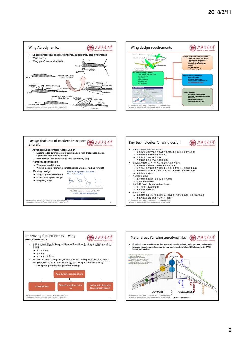
2018/3/11 2 © Shanghai Jiao Tong University – Dr. Wenbin Song School of Aeronautics and Astronautics, 2017-2018 Wing Aerodynamics • Speed range: low speed, transonic, supersonic, and hypersonic • Wing areas • Wing planform and airfoils © Shanghai Jiao Tong University – Dr. Wenbin Song School of Aeronautics and Astronautics, 2017-2018 Performance requirements Lift at given incidence/altitude Low take-off drag High CLmax Minimum weight Handling quality Low complexity Low cost Wing design requirements 8 Design constraints/considerations Landing gear integration Leading edge/trailing edge shaping Front spar/Rear spar locations VHBP engine integration Wing Flap/Slat Integration and Kinematics Roll-control layout Landing gear integration Potential key technologies Active load control Differential flap settings Variable camber control for cruise New materials/aeroelastics Design methods Advanced airfoil optimization Integrated wing/engine/faring/winglet optimization Advanced high lift devices Minimum interference drag © Shanghai Jiao Tong University – Dr. Wenbin Song School of Aeronautics and Astronautics, 2017-2018 Design features of modern transport aircraft • Advanced Supercritical Airfoil Design – Leading edge optimization in combination with droop nose design – Optimized rear-loading design – More robust (less sensitive to flow conditions, etc) • Planform optimization – Wing root modification – Wingtip design(blending winglet, raked winglet, folding winglet) • 3D wing design – Wing/Engine interference – Robust Multi-point design – Morphing wing 9 © Shanghai Jiao Tong University – Dr. Wenbin Song School of Aeronautics and Astronautics, 2017-2018 Key technologies for wing design • 机翼设计的基本需求(相互矛盾) – 满足给定巡航速度下的升力需求条件下的阻力最小(与结构重量要求矛盾) – 低速起降特性(与巡航设计要求矛盾) – 结构重量轻(与阻力最小矛盾) – 足够的油箱空间(与气动设计要求矛盾) • 巡航速度的提高(0.82-0.85)需要优化技术的应用 – 更先进的翼型(升阻比,激波/边界层干扰,后缘) – 使用优化技术的三维外形的系统修型技术(内翼修型技术,前后缘修型技术) – 一体化设计(机翼/尾翼,翼身,机翼/小翼,翼身短舱,带动力一体化等) – 主被动流动控制技术 • 与结构设计的融合 – 复材结构使得翼展进一步加大,提升气动效率 – 结构/气动一体化设计 • 载荷控制(load alleviation function)- – 进一步发展(多功能控制面) – 更复杂的燃油管理方案 • 缩短设计时间 – 数据管理与交换方法(不同分析模块、试验数据,飞行试验数据)-标准化格式和流程 – 缩短风洞试验时间(模型3D,与CFD相结合) 10 © Shanghai Jiao Tong University – Dr. Wenbin Song School of Aeronautics and Astronautics, 2017-2018 Improving fuel efficiency – wing aerodynamics • 基于飞机的航程公式(Breguet Range Equations),提高飞机航段效率的技 术措施 – 发动机的油耗 – 结构效率 – 气动效率(升阻比) • An aircraft with a high lift/drag ratio at the highest possible Mach No. (before the drag divergence), but wing is also limited by – Low speed performance (takeoff/landing) 11 Cruise M*L/D Takeoff and climb-out at V2 Landing with flaps with low approach speed Aerodynamic considerations © Shanghai Jiao Tong University – Dr. Wenbin Song School of Aeronautics and Astronautics, 2017-2018 Major areas for wing aerodynamics • Flow basics remain the same, but more advanced methods, tools, process, and criteria • Increase in cruise speed enabled by more advanced airfoil and 3D shaping with RANS- based optimization 12 A310 wing A350XWB wing 20 years Source: Airbus FAST
2018/3/11 Evolution of A350 wing (with HLD) 圈上清文大学 国上清大学 Two inboard droop nose devicesingle droop nose device Six spoilers seven spoilers Two outboard ailerons ·Six outboard slats Single advanced dropped hinge flap Section A AIRFOIL Soor an0 Airfoil Geometry Definition 圈上活大坐 Some Definitions of Airfoil Thickness,Camberline 圆上洋文廷大整 .Thickness thickness(t) L.E.Radius Slope Camberine目m后-asg-asn目oa目-aof目j] Mean Line 以÷-且 ·Leading edge radius Angle of attack Curvature -产且 - Leading Edge Chord(e) Trailing edge Airfoil shape:the cross section of a wing s目 rAer 8oa6o0e四k-a88 Typical airfoil geometry 图上洋大峰 Airfoil flow 园上海发大坐 AIRFOIL AND GEOMETRY SELECTION 43 Lift coefficient C= ge NACA d ge Moment coefficientC= 2025e0 c chord length ,↓pr2 dyuamic pressure L=pV 5C路话D UIUC Airfoil Data site:http://www.ae.uiuc.edu/m-selig/ads.html 3
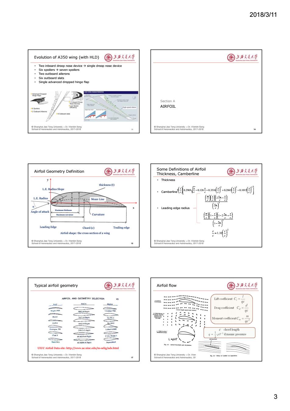
2018/3/11 3 © Shanghai Jiao Tong University – Dr. Wenbin Song School of Aeronautics and Astronautics, 2017-2018 Evolution of A350 wing (with HLD) • Two inboard droop nose device single droop nose device • Six spoilers seven spoilers • Two outboard ailerons • Six outboard slats • Single advanced dropped hinge flap 13 © Shanghai Jiao Tong University – Dr. Wenbin Song School of Aeronautics and Astronautics, 2017-2018 AIRFOIL Section A 14 © Shanghai Jiao Tong University – Dr. Wenbin Song School of Aeronautics and Astronautics, 2017-2018 Airfoil Geometry Definition 15 Airfoil shape: the cross section of a wing αAngle of attack thickness (t) L.E. Radius Slope L.E. Radius Leading Edge Chord (c) Trailing edge Mean Line Curvature Maximum thickness Maximum curvature x y © Shanghai Jiao Tong University – Dr. Wenbin Song School of Aeronautics and Astronautics, 2017-2018 Some Definitions of Airfoil Thickness, Camberline • Thickness • Camberline • Leading edge radius 2 3 4 5 0.2969 0.126 0.3516 0.2843 0.1015 c x c x c x c x c x c t 2 2 c x c x c x c x c m m m 2 1 1 1 2 c x c x c x c x c m m m 2 1.10 c t c r © Shanghai Jiao Tong University – Dr. Wenbin Song School of Aeronautics and Astronautics, 2017-2018 Typical airfoil geometry 17 UIUC Airfoil Data site: http://www.ae.uiuc.edu/m-selig/ads.html © Shanghai Jiao Tong University – Dr. Wenbin Song School of Aeronautics and Astronautics, 2017-2018 Airfoil flow qc l Cl qc d Cd 2 qc m Cm Lift coefficient Drag coefficient Moment coefficient chord length dynamic pressure c 2 2 1 q V L =ρVΓ
2018/3/11 Classification of common airfoils 国上唐美大坐 Aerodynamic properties of airfoils 国上清大学 Aerodynamic features Aerodynamic properties -Laminar flow airfoils =15pm2d -Supercritical airfolls Clmax -High-lift airfoils -Lift curve slope Cla Celmax -Supersonic airfoils -Zero lift angle of attack od -Zero lift moment -Low-moment airfoils ·Roles Lift-drag ratio ·Design Methods Fix-wing aircraft -Traditionally,aerodynamic properties were determined by wing tunnel -Helicopter rotor airfoils test -Turbine blade airfoils -There are ma starting point for new design ent families of airfoils that can be used as Axial flow cooling fan Modern airfoils are more likely to be designed based on CFD codes Engine compressors using optimization or inverse design methods r nd 7 What constitute a better airfoil 国上活美大坐 NACA Airfoils(I) 圆上洋发廷大坐 Desired airfoil aerodynamic characteristics Developed by NACAfor use with low-speed aircrat -High design lift coefficient 4-series (NACA-ABCD) -High max lift coefficient -Small drag coefficient -Small zerc -tift oitch moment -High drag divergence Mach number 5-series (NACA-ABCDE) Impact on Aircraft Performance A :designed CL/0.1S; -High dl beneficial to take-off/landing/maneuverring BC:2*distance to maximum camber toLE -Small drag coefficient relates to max speed -High cmax beneficial to take-off/landing/maneuverring nce -High lift/drag ratio leads to better range 6-series (NACA-ABC-DEF),first laminar flow airfoils -Small zero-lift moment leads to small trim drag the series eesnod D:design CL in tenth EF:maximum thickness in tens of percent of chord eagaea2-w58 NACA Airfoils(II) 国上洋大坐 NACA 642-2153 million<Re<9 million; std.roughness at Re=6 million 园上声戈是大学 7-series (NACA-ABCDEFG).further develo nent from six-series pressure zones achieved separately on upper and lower C.Cm~alpha Split flap d=60P ries indicator -B:distance o the minimum pressure area in tens of percent of chord ca ~C pper minimum pressure area in tens of percent of chord -D:a letter referring to a standard profile from earlier NACA series -E:design CL in nth Noflap Drag FG:maximum thi ess in tens of percent of chord bucket 8-series (supercritical airfoils) -Identification similar to 7-seris -Designed to independently maximum airfoil above and below the wing Cm.c/ 23 Angle ofattack Section Lift Coefficient 4
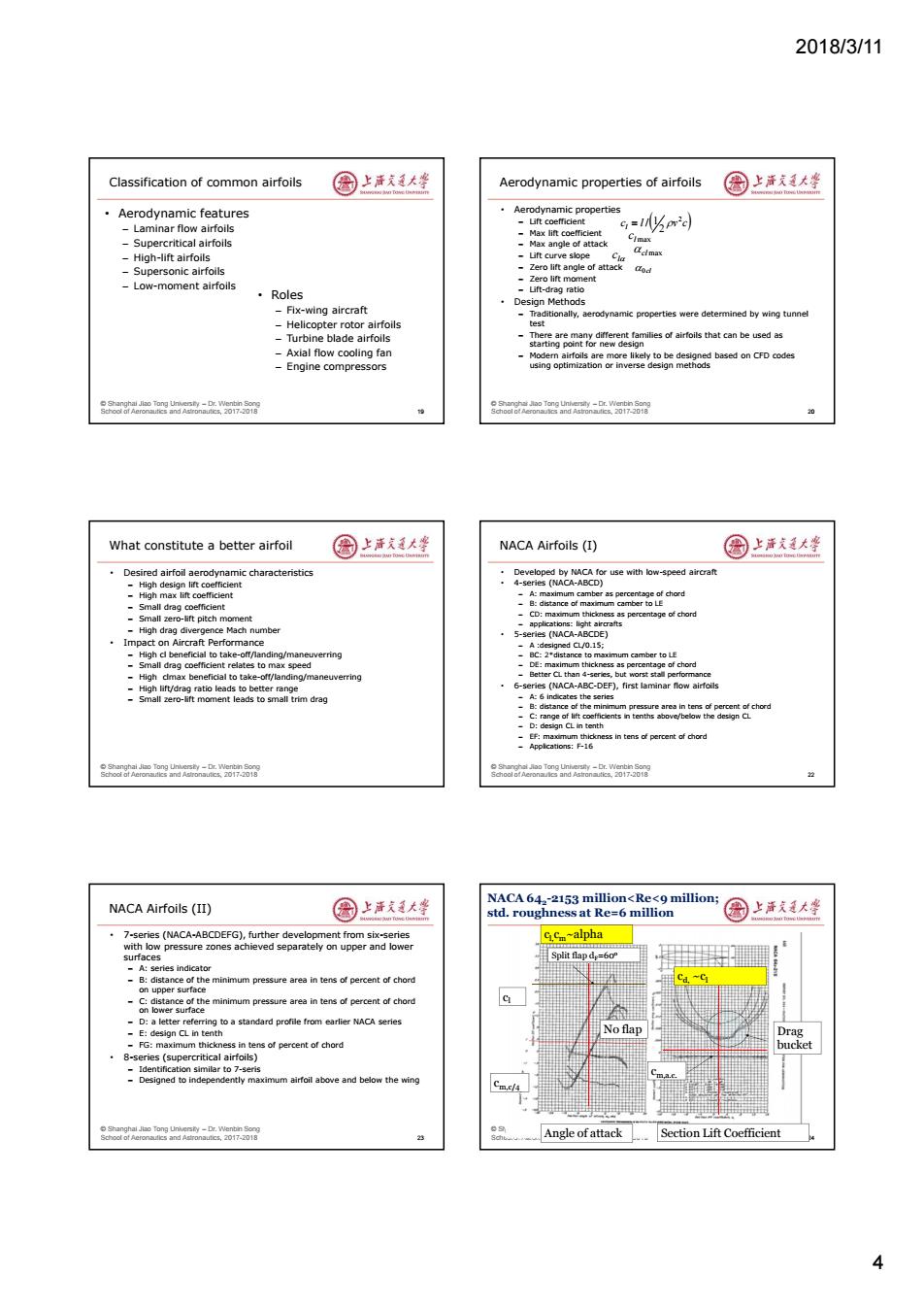
2018/3/11 4 © Shanghai Jiao Tong University – Dr. Wenbin Song School of Aeronautics and Astronautics, 2017-2018 Classification of common airfoils • Aerodynamic features – Laminar flow airfoils – Supercritical airfoils – High-lift airfoils – Supersonic airfoils – Low-moment airfoils 19 • Roles – Fix-wing aircraft – Helicopter rotor airfoils – Turbine blade airfoils – Axial flow cooling fan – Engine compressors © Shanghai Jiao Tong University – Dr. Wenbin Song School of Aeronautics and Astronautics, 2017-2018 Aerodynamic properties of airfoils • Aerodynamic properties – Lift coefficient – Max lift coefficient – Max angle of attack – Lift curve slope – Zero lift angle of attack – Zero lift moment – Lift-drag ratio • Design Methods – Traditionally, aerodynamic properties were determined by wing tunnel test – There are many different families of airfoils that can be used as starting point for new design – Modern airfoils are more likely to be designed based on CFD codes using optimization or inverse design methods 20 c l v c l 2 2 / 1 l max c l c cl max 0cl © Shanghai Jiao Tong University – Dr. Wenbin Song School of Aeronautics and Astronautics, 2017-2018 What constitute a better airfoil • Desired airfoil aerodynamic characteristics – High design lift coefficient – High max lift coefficient – Small drag coefficient – Small zero-lift pitch moment – High drag divergence Mach number • Impact on Aircraft Performance – High cl beneficial to take-off/landing/maneuverring – Small drag coefficient relates to max speed – High clmax beneficial to take-off/landing/maneuverring – High lift/drag ratio leads to better range – Small zero-lift moment leads to small trim drag © Shanghai Jiao Tong University – Dr. Wenbin Song School of Aeronautics and Astronautics, 2017-2018 NACA Airfoils (I) • Developed by NACA for use with low-speed aircraft • 4-series (NACA-ABCD) – A: maximum camber as percentage of chord – B: distance of maximum camber to LE – CD: maximum thickness as percentage of chord – applications: light aircrafts • 5-series (NACA-ABCDE) – A :designed CL/0.15; – BC: 2*distance to maximum camber to LE – DE: maximum thickness as percentage of chord – Better CL than 4-series, but worst stall performance • 6-series (NACA-ABC-DEF), first laminar flow airfoils – A: 6 indicates the series – B: distance of the minimum pressure area in tens of percent of chord – C: range of lift coefficients in tenths above/below the design CL – D: design CL in tenth – EF: maximum thickness in tens of percent of chord – Applications: F-16 22 © Shanghai Jiao Tong University – Dr. Wenbin Song School of Aeronautics and Astronautics, 2017-2018 NACA Airfoils (II) • 7-series (NACA-ABCDEFG), further development from six-series with low pressure zones achieved separately on upper and lower surfaces – A: series indicator – B: distance of the minimum pressure area in tens of percent of chord on upper surface – C: distance of the minimum pressure area in tens of percent of chord on lower surface – D: a letter referring to a standard profile from earlier NACA series – E: design CL in tenth – FG: maximum thickness in tens of percent of chord • 8-series (supercritical airfoils) – Identification similar to 7-seris – Designed to independently maximum airfoil above and below the wing 23 © Shanghai Jiao Tong University – Dr. Wenbin Song School of Aeronautics and Astronautics, 2017-2018 24 Split flap dF=60o No flap cl cm,c/4 Drag bucket cm,a.c. Angle of attack Section Lift Coefficient NACA 642 -2153 million<Re<9 million; std. roughness at Re=6 million cl,cm~alpha cd, ~cl

2018/3/11 Aerodynamic Effect of Airfoil Parameters 园上声克大婆 Airfoil Stall Characteristics 国上清大学 ,LE Radius(缘辛径)-lift coefficient,wave drag,transition Different stall characteristics for airfoils with different leading edge radius.thickness Thickness-to-chord ratio(t/c,相对厚度)-wave drag,stall Different airfoil sections can be used at the wing root and tip characteristics,lift coefficient,and structural weight Stall characteristics(失速特性) (round LE,14%t/c),separation start from TE,and loss of lift Fat airfoils Thinner airfoils Very thin airfoils Thinner airfoil (6-14%t/c),stall from the LE SEPARATION BUBBLE 螺 AE 宽RTD o r nd 0171 Soor an0 Structural Effect of Airfoil Parameters 圆上清文大些 Transonic Airfoils 国上清支大峰 Smaller weight for higher t/c value For high speed airfoils,the flow accelerates to supersonic over the More volume for higher t/c value,often imposed as constraints upper surface,forming shock wave,leading to high wave drag onstraints at certain chord locations to accommodate One solution is to use supercritical airfoils Where the shock wave is minimized or even eliminated Smaller range for C.G.Range,better for structural design eagaea2-w58 8oa6o0e四k-a88 Supercritical airfoil(超临界翼型) 国上洋大坐 Flow over conventional and supercritical airfoils 图上活大坐 Intuitive reasoning Pressure Strong shock distributions wave Extending the drag divergence Mach Number SC()designed mainly by contour modification and wind tunnel testing SC(D)designed using transonic,viscous analysis code 5
2018/3/11 5 © Shanghai Jiao Tong University – Dr. Wenbin Song School of Aeronautics and Astronautics, 2017-2018 Aerodynamic Effect of Airfoil Parameters • LE Radius(前缘半径) – lift coefficient, wave drag, transition • Thickness-to-chord ratio (t/c,相对厚度) – wave drag, stall characteristics, lift coefficient, and structural weight • Stall characteristics(失速特性) – Fat airfoil (round LE, 14%t/c), separation start from TE, and loss of lift is gradual – Thinner airfoil (6-14%t/c), stall from the LE © Shanghai Jiao Tong University – Dr. Wenbin Song School of Aeronautics and Astronautics, 2017-2018 Airfoil Stall Characteristics • Different stall characteristics for airfoils with different leading edge radius, thickness • Different airfoil sections can be used at the wing root and tip Fat airfoils Thinner airfoils Very thin airfoils © Shanghai Jiao Tong University – Dr. Wenbin Song School of Aeronautics and Astronautics, 2017-2018 Structural Effect of Airfoil Parameters • Smaller weight for higher t/c value • More volume for higher t/c value, often imposed as constraints • t/c value constraints at certain chord locations to accommodate spar structure • Smaller range for C.G. Range, better for structural design © Shanghai Jiao Tong University – Dr. Wenbin Song School of Aeronautics and Astronautics, 2017-2018 Transonic Airfoils • For high speed airfoils, the flow accelerates to supersonic over the upper surface, forming shock wave, leading to high wave drag • One solution is to use supercritical airfoils – Where the shock wave is minimized or even eliminated © Shanghai Jiao Tong University – Dr. Wenbin Song School of Aeronautics and Astronautics, 2017-2018 Supercritical airfoil(超临界翼型) 29 Extending the drag divergence Mach Number SC(I) designed mainly by contour modification and wind tunnel testing SC(II) designed using transonic, viscous analysis code Increased drag divergence angle, but increased friction drag Intuitive reasoning © Shanghai Jiao Tong University – Dr. Wenbin Song School of Aeronautics and Astronautics, 2017-2018 Flow over conventional and supercritical airfoils 30 Pressure Strong shock distributions wave