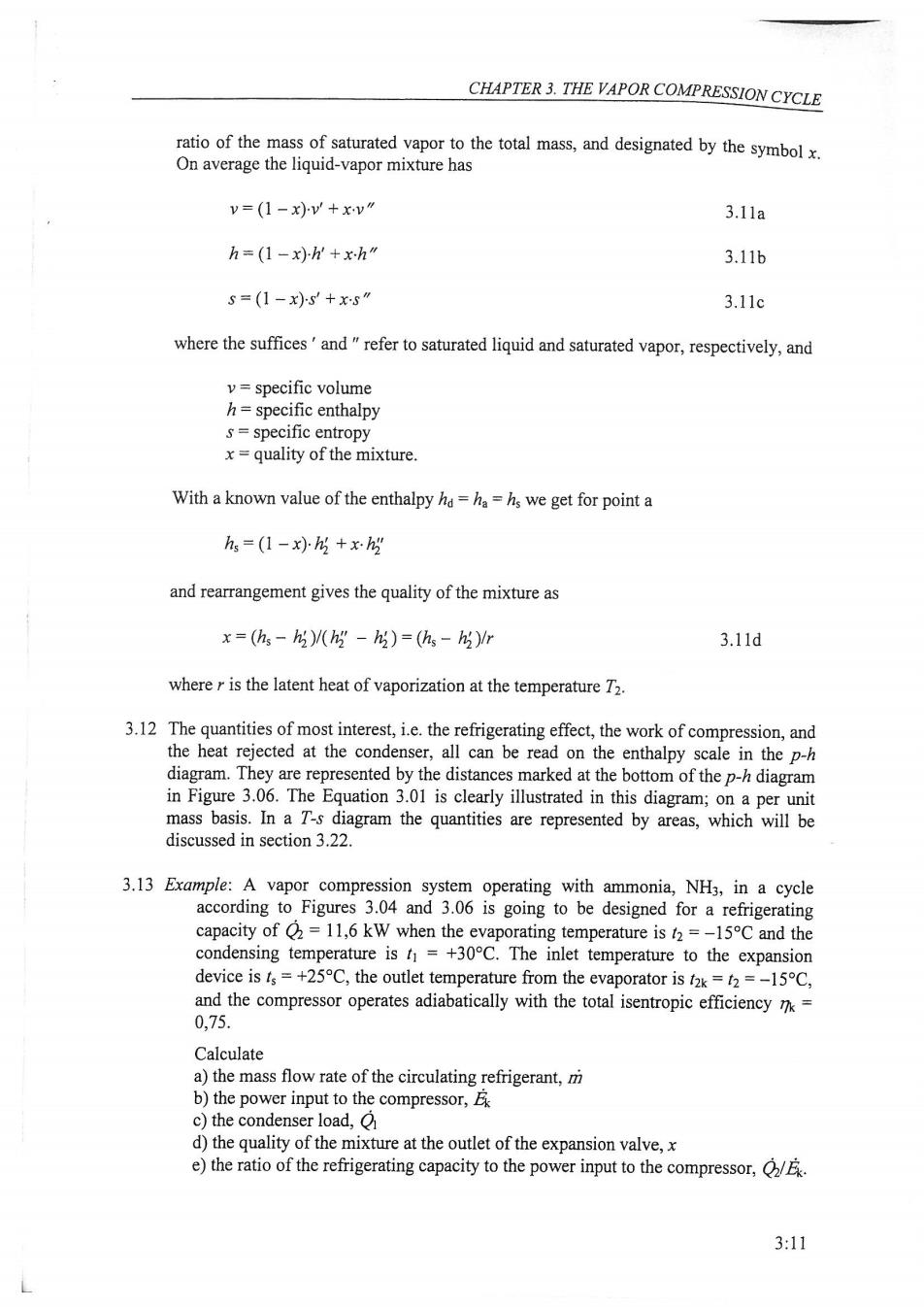
CHAPTER 3.THE VAPOR COMPRESSION CYCLE ratio of the mass of saturated vapor to the total mass,and designated by the symbolx. On average the liquid-vapor mixture has v=(1-x)v'+xv" 3.11a h=(1-x)h'+xh" 3.11b 5=(1-x)S+xS" 3.11c where the suffices'and"refer to saturated liquid and saturated vapor,respectively,and v=specific volume h=specific enthalpy s=specific entropy x=quality of the mixture. With a known value of the enthalpy hd =ha=hs we get for point a hs=(1-x).h +x.h2" and rearrangement gives the quality of the mixture as x=(h-h3)/(h3-h3)=(h-h3)r 3.11d where r is the latent heat of vaporization at the temperature T2. 3.12 The quantities of most interest,i.e.the refrigerating effect,the work of compression,and the heat rejected at the condenser,all can be read on the enthalpy scale in the p-h diagram.They are represented by the distances marked at the bottom of the p-h diagram in Figure 3.06.The Equation 3.01 is clearly illustrated in this diagram;on a per unit mass basis.In a T-s diagram the quantities are represented by areas,which will be discussed in section 3.22. 3.13 Example:A vapor compression system operating with ammonia,NH3,in a cycle according to Figures 3.04 and 3.06 is going to be designed for a refrigerating capacity of =11,6 kW when the evaporating temperature is t2=-15C and the condensing temperature is t=+30C.The inlet temperature to the expansion device is fs=+25C,the outlet temperature from the evaporator is tak=t2=-15C, and the compressor operates adiabatically with the total isentropic efficiency T= 0,75. Calculate a)the mass flow rate of the circulating refrigerant,m b)the power input to the compressor,E c)the condenser load,O d)the quality of the mixture at the outlet of the expansion valve,x e)the ratio of the refrigerating capacity to the power input to the compressor,/E. 3:11

REFRIGERATING ENGINEERING Solution:From tables and diagrams for thermodynamic properties of the refrigerant ammonia we find the following. a)The table gives hak 1444,21 kJ/kg and hs =317,89 kJ/kg.Applying Equation 3.07b, m=22/h2k-hs)=11,6/(1444,21-317,89)=0.0103kgs. b)The diagram gives hik.is=1676 kJ/kg and Equation 3.08e gives h1k=h2k+(h1kis-h2k)/k=1444,21+(1676-1444,21)/0,75=1753,3kJ/kg and according to Equation 3.08g the power input to the compressor is Ek=m(h1k-h2k)=0,0103(1753,3-1444,21)=3.18kW. c)From Equation 3.09b,the condenser load is 9=m(h1k-hs)=0,0103(1753,3-317,89)=14.78kW which is checked with Equation 3.09c 91=92+Ek=11,6+3,18=14,78kW. d)From the p-h diagram we find x=0,14,i.e.14%of the refrigerant mass vaporizes in the expansion valve.The accuracy of the result is increased by applying Equation 3.11d,withh=hak and h=131,29 kJ/kg,yielding x=(h-)/(h5-)=(317,89-131,29)/(1444,21-131,29)=0.142 e)The ratio of the refrigerating capacity to the power input to the compressor is a figure of merit of the cycle,and it is called the coefficient of performance of the refrigeration cycle,COP2.It gives the ratio of that what we gained to that what we sacrificed.In this case the coefficient of performance is C0P2k=22/Ek=11,6/3,18=3.65. The refrigerating capacity is 3,65 times the power input to the compressor in this example.Alternatively, C0P2k=92/a=(h2k-hs)/h1k-h2k)=(1444,2-317,9)/(1753,3-1444,2)=3,65. 3:12