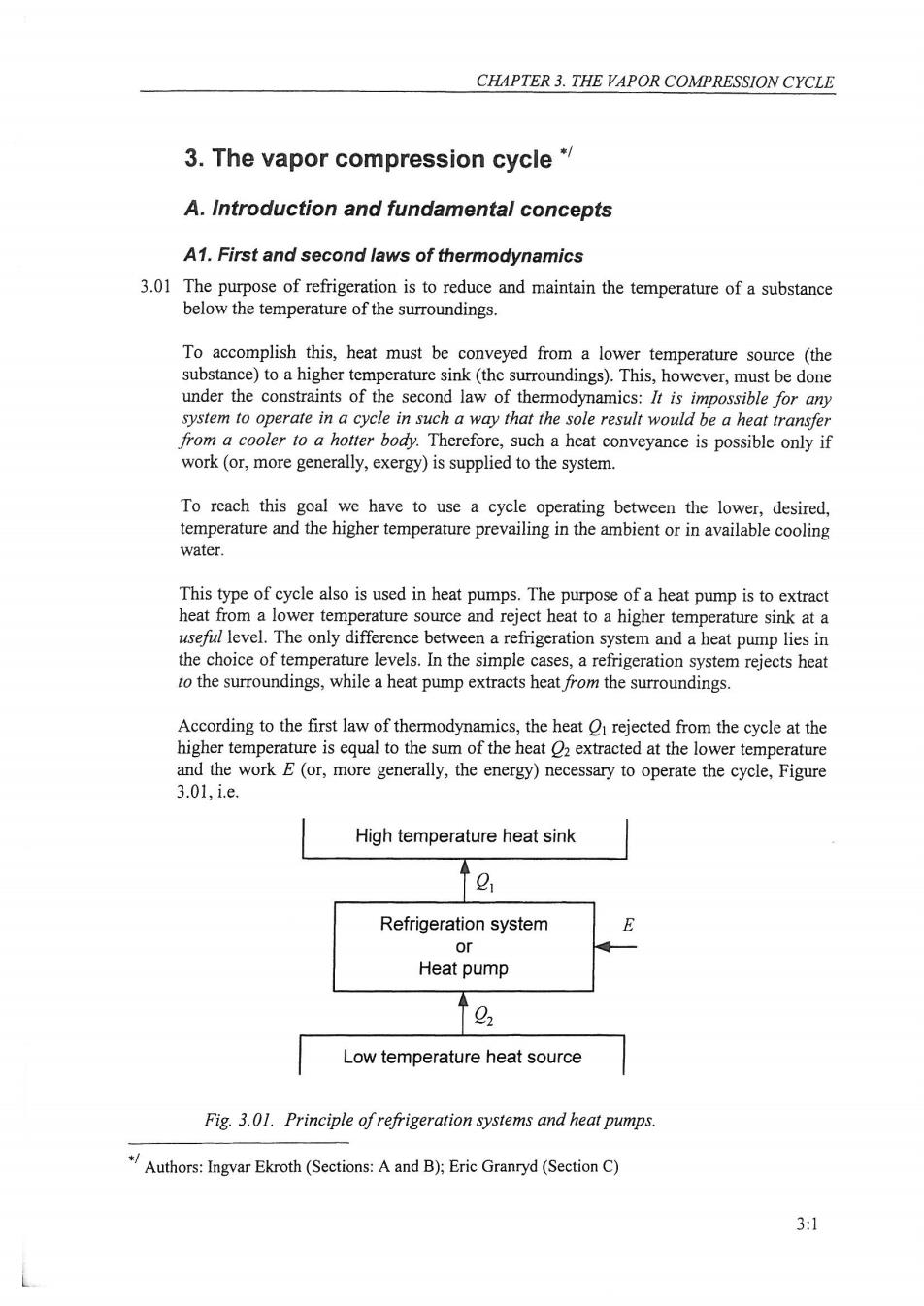
CHAPTER 3.THE VAPOR COMPRESSION CYCLE 3.The vapor compression cycle* A.Introduction and fundamental concepts A1.First and second laws of thermodynamics 3.01 The purpose of refrigeration is to reduce and maintain the temperature of a substance below the temperature of the surroundings. To accomplish this,heat must be conveyed from a lower temperature source (the substance)to a higher temperature sink(the surroundings).This,however,must be done under the constraints of the second law of thermodynamics:It is impossible for any system to operate in a cycle in such a way that the sole result would be a heat transfer from a cooler to a hotter body.Therefore,such a heat conveyance is possible only if work (or,more generally,exergy)is supplied to the system. To reach this goal we have to use a cycle operating between the lower,desired, temperature and the higher temperature prevailing in the ambient or in available cooling water. This type of cycle also is used in heat pumps.The purpose of a heat pump is to extract heat from a lower temperature source and reject heat to a higher temperature sink at a useful level.The only difference between a refrigeration system and a heat pump lies in the choice of temperature levels.In the simple cases,a refrigeration system rejects heat to the surroundings,while a heat pump extracts heat from the surroundings. According to the first law of thermodynamics,the heat O rejected from the cycle at the higher temperature is equal to the sum of the heat 2 extracted at the lower temperature and the work E(or,more generally,the energy)necessary to operate the cycle,Figure 3.01,i.e. High temperature heat sink g Refrigeration system E or Heat pump 0 Low temperature heat source Fig.3.01.Principle of refrigeration systems and heat pumps. Authors:Ingvar Ekroth(Sections:Aand B):Eric Granryd (Section C) 3:1

REFRIGERATING ENGINEERING O1=02+E 3.01 The net energy input E,which is required to lift the heat O2 from the lower to the higher temperature,need not necessarily be mechanical work.For example in an absorption refrigeration system heat from a high temperature source is used to operate the cycle, and in an ejector(vacuum)refrigeration system kinetic energy is used. A2.Carnot cycle 3.02 Theoretically,among many other possibilities,we can make use of the reversible Carnot cycle.As Figure 3.02 depicts,the cycle is operated in the anti-clockwise direction between the temperatures T2 and T1.The working fluid executes four reversible processes in the cycle: T E a b Fig.3.02.The Carnot cycle in a temperature-entropy (T-s)diagram. a>b:isothermal expansion at T2 while heat 2 is transferred to the working fluid from the heat source b->c:isentropic compression from T2 to Ti without any heat transfer c->d:isothermal compression at Ti while heat O is transferred from the working fluid to the heat sink d>a:isentropic expansion from Ti to T2 without any heat transfer. The net work input supplied to the working fluid during the cycle is denoted E,and the first law of thermodynamics,Equation 3.01,gives E=O1-O2. A3.Principle of the vapor compression cycle 3.03 In actual applications of refrigeration,cycles operated with mechanical work are predominant.All vapor compression systems function in that way. The working fluid in a vapor compression system is called a refrigerant.In this introductory chapter the discussions are restricted to cycles operating with refrigerants 3:2
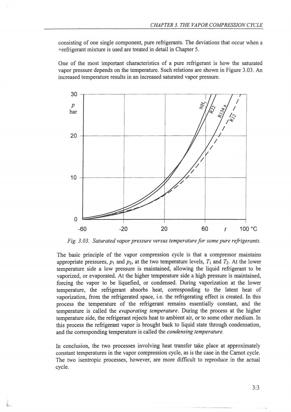
CHAPTER 3.THE VAPOR COMPRESSION CYCLE consisting of one single component,pure refrigerants.The deviations that occur when a +refrigerant mixture is used are treated in detail in Chapter 5. One of the most important characteristics of a pure refrigerant is how the saturated vapor pressure depends on the temperature.Such relations are shown in Figure 3.03.An increased temperature results in an increased saturated vapor pressure. 30 p NH: bar R134a e 20 10 0 -60 -20 20 60 t 100C Fig.3.03.Saturated vapor pressure versus temperature for some pure refrigerants. The basic principle of the vapor compression cycle is that a compressor maintains appropriate pressures,pi and p2,at the two temperature levels,T and T2.At the lower temperature side a low pressure is maintained,allowing the liquid refrigerant to be vaporized,or evaporated.At the higher temperature side a high pressure is maintained, forcing the vapor to be liquefied,or condensed.During vaporization at the lower temperature,the refrigerant absorbs heat,corresponding to the latent heat of vaporization,from the refrigerated space,i.e.the refrigerating effect is created.In this process the temperature of the refrigerant remains essentially constant,and the temperature is called the evaporating temperature.During the process at the higher temperature side,the refrigerant rejects heat to ambient air,or to some other medium.In this process the refrigerant vapor is brought back to liquid state through condensation, and the corresponding temperature is called the condensing temperature. In conclusion,the two processes involving heat transfer take place at approximately constant temperatures in the vapor compression cycle,as is the case in the Carnot cycle. The two isentropic processes,however,are more difficult to reproduce in the actual cycle. 3:3
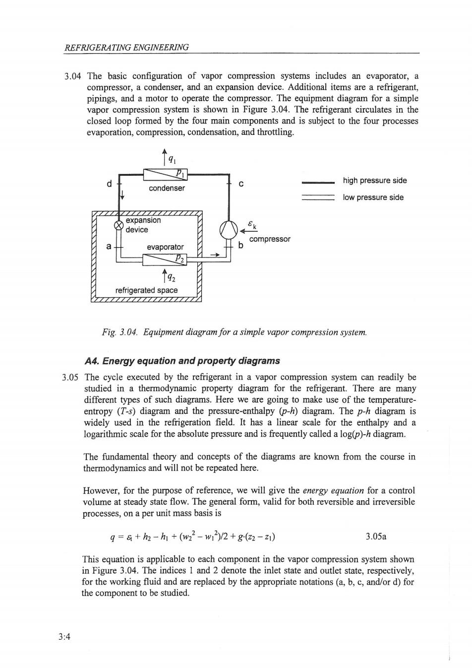
REFRIGERATING ENGINEERING 3.04 The basic configuration of vapor compression systems includes an evaporator,a compressor,a condenser,and an expansion device.Additional items are a refrigerant, pipings,and a motor to operate the compressor.The equipment diagram for a simple vapor compression system is shown in Figure 3.04.The refrigerant circulates in the closed loop formed by the four main components and is subject to the four processes evaporation,compression,condensation,and throttling. high pressure side condenser low pressure side expansion device compressor a evaporator 个92 refrigerated space Fig.3.04.Equipment diagram for a simple vapor compression system. A4.Energy equation and property diagrams 3.05 The cycle executed by the refrigerant in a vapor compression system can readily be studied in a thermodynamic property diagram for the refrigerant.There are many different types of such diagrams.Here we are going to make use of the temperature- entropy (T-s)diagram and the pressure-enthalpy (p-h)diagram.The p-h diagram is widely used in the refrigeration field.It has a linear scale for the enthalpy and a logarithmic scale for the absolute pressure and is frequently called a log(p)-h diagram. The fundamental theory and concepts of the diagrams are known from the course in thermodynamics and will not be repeated here. However,for the purpose of reference,we will give the energy equation for a control volume at steady state flow.The general form,valid for both reversible and irreversible processes,on a per unit mass basis is g=a+h2-h1+(w22-w1)/2+g(22-z1) 3.05a This equation is applicable to each component in the vapor compression system shown in Figure 3.04.The indices 1 and 2 denote the inlet state and outlet state,respectively, for the working fluid and are replaced by the appropriate notations(a,b,c,and/or d)for the component to be studied. 3:4

CHAPTER 3.THE VAPOR COMPRESSION CYCLE In the equation q net amount of heat transferred to the working fluid =net amount of shaft work delivered from the working fluid h specific enthalpy for the working fluid w=velocity of the working fluid z elevation above an arbitrarily datum level g =acceleration due to gravity. In vapor compression systems,changes in the potential energy (gz)are mostly negligible,and so are normally changes in the kinetic energy(w/2),leaving the energy equation in the simple form q=a+h2-h 3.05b Important notice:Heat transfer and work per unit mass exposed to a process are designated by the lower-case letters g and &respectively.The unit for g and eis J/kg or kJ/kg.The total amount of heat transfer and work in J or kJ are designated by the capital letters O and E,and are obtained from g and &by multiplication with the mass m in kg involved in the process,e.g.O=m.q.The corresponding rates of energy transfer in W or kW are symbolized by a dot,i.e.Oand E,and the multiplication is now with the mass flow rate m in kg/s,e.g.Q=mq.(Later on,in sections 3.30 and 3.32,two volumetric quantities gv and in J/m'or kJ/m'are introduced.) B.Simple vapor compression cycle B1.The simple cycle in T-s and p-h diagrams 3.06 Figure 3.06 shows the cycle for a simple vapor compression system according to Figure 3.04 in T-s and p-h diagrams.As explained previously,the main part of the cycle is executed in the wet region(also called the liquid-vapor saturation region,the two-phase region or the vapor dome),where the refrigerant undergoes vaporization and condensation.The compressor and the expansion device maintain a high pressure side, with the pressure pi,and a low pressure side,with the pressure p2.The corresponding condensing temperature and evaporating temperature are denoted Ti and T2, respectively. 3.07 The evaporator is a container or a pipe system wherein the refrigerant vaporizes at a low temperature.The latent heat of vaporization is taken from the surroundings of the evaporator,in this case the air in a refrigerated space.Heat is removed from that space and the temperature in the space is kept at a low,desired,level. The compressor sucks away the formed vapor,thereby keeping the pressure at a low level,allowing the vaporization to be maintained.To make the heat transfer possible, from the air in the refrigerated space to the refrigerant,the boiling temperature of the refrigerant,i.e.the evaporating temperature,has to be below the temperature of the air in the refrigerated space. 3:5