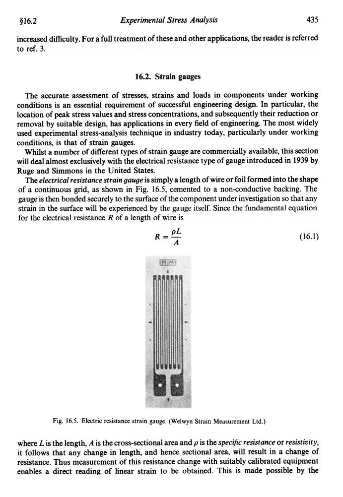
$16.2 Experimental Stress Analysis 435 increased difficulty.For a full treatment of these and other applications,the reader is referred to ref.3. 16.2.Strain gauges The accurate assessment of stresses,strains and loads in components under working conditions is an essential requirement of successful engineering design.In particular,the location of peak stress values and stress concentrations,and subsequently their reduction or removal by suitable design,has applications in every field of engineering.The most widely used experimental stress-analysis technique in industry today,particularly under working conditions,is that of strain gauges. Whilst a number of different types of strain gauge are commercially available,this section will deal almost exclusively with the electrical resistance type of gauge introduced in 1939 by Ruge and Simmons in the United States. The electrical resistance strain gauge is simply a length of wire or foil formed into the shape of a continuous grid,as shown in Fig.16.5,cemented to a non-conductive backing.The gauge is then bonded securely to the surface of the component under investigation so that any strain in the surface will be experienced by the gauge itself.Since the fundamental equation for the electrical resistance R of a length of wire is R= (16.1) A HE Fig.16.5.Electric resistance strain gauge.(Welwyn Strain Measurement Ltd.) where L is the length,A is the cross-sectional area and p is the specific resistance or resistivity, it follows that any change in length,and hence sectional area,will result in a change of resistance.Thus measurement of this resistance change with suitably calibrated equipment enables a direct reading of linear strain to be obtained.This is made possible by the
Experimental Stress Analysis 435 §16.2 increased difficulty. For a full treatment of these and other applications, the reader is referred to ref. 3. . 16.2. Strain gauges The accurate assessment of stresses, strains and loads in components under working conditions is an essential requirement of successful engineering design. In particular, the location of peak stress values and stress concentrations, and subsequently their reduction or removal by suitable design, has applications in every field of engineering. The most widely used experimental stress-analysis technique in industry today, particularly under working conditions, is that of strain gauges. Whilst a number of different types of strain gauge are commercially available, this section will deal almost exclusively with the electrical resistance type of gauge introduced in 1939 by Ruge and Simmons in the United States. The electrical resistance strain gauge is simply a length of wire or foil formed into the shape of a continuous grid, as shown in Fig. 16.5, cemented to a non-conductive backing. The gauge is then bonded securely to the surface of the component under investigation so that any strain in the surface will be experienced by the gauge itself. Since the fundamental equation for the electrical resistance R of a length of wire is R=~ A (16.1) Fig. 16.5. Electric resistance strain gauge. (Welwyn Strain Measurement lId.) where L is the length, A is the cross-sectional area and p is the spec!fic resistance or resistivity, it follows that any change in length, and hence sectional area, will result in a change of resistance. Thus measurement of this resistance change with suitably calibrated equipment enables a direct reading of linear strain to be obtained. This is made possible by the
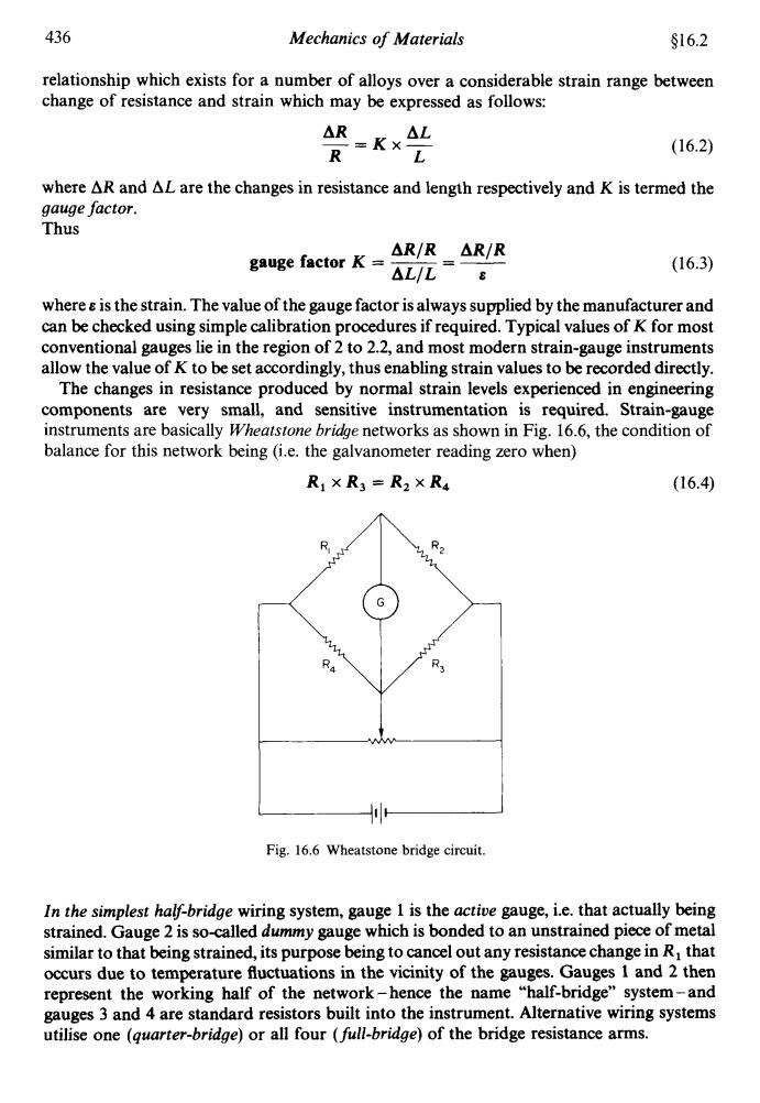
436 Mechanics of Materials $16.2 relationship which exists for a number of alloys over a considerable strain range between change of resistance and strain which may be expressed as follows: △Rx△L =Kx- R (16.2) L where AR and AL are the changes in resistance and length respectively and K is termed the gauge factor. Thus △R/R△R/R gauge factor K △L/L8 (16.3) where is the strain.The value of the gauge factor is always supplied by the manufacturer and can be checked using simple calibration procedures if required.Typical values of K for most conventional gauges lie in the region of 2 to 2.2,and most modern strain-gauge instruments allow the value of K to be set accordingly,thus enabling strain values to be recorded directly. The changes in resistance produced by normal strain levels experienced in engineering components are very small,and sensitive instrumentation is required.Strain-gauge instruments are basically Wheatstone bridge networks as shown in Fig.16.6,the condition of balance for this network being (i.e.the galvanometer reading zero when) R1×R3=R2XR4 (16.4) R 2 R3 Fig.16.6 Wheatstone bridge circuit. In the simplest half-bridge wiring system,gauge 1 is the active gauge,i.e.that actually being strained.Gauge 2 is so-called dummy gauge which is bonded to an unstrained piece of metal similar to that being strained,its purpose being to cancel out any resistance change in R that occurs due to temperature fluctuations in the vicinity of the gauges.Gauges 1 and 2 then represent the working half of the network-hence the name "half-bridge"system-and gauges 3 and 4 are standard resistors built into the instrument.Alternative wiring systems utilise one (guarter-bridge)or all four (full-bridge)of the bridge resistance arms
436 Mechanics of Materials $16.2 relationship which exists for a number of alloys over a considerable strain range between change of resistance and strain which may be expressed as follows: AR AL R L -=Kx- (16.2) where AR and AL are the changes in resistance and length respectively and K is termed the gauge factor. Thus ARfR ARfR gauge factor K = - ALfL - - 7 (16.3) where e is the strain. The value of the gauge factor is always supplied by the manufacturer and can be checked using simple calibration procedures if required. Typical values of K for most conventional gauges lie in the region of 2 to 2.2, and most modern strain-gauge instruments allow the value of K to be set accordingly, thus enabling strain values to be recorded directly. The changes in resistance produced by normal strain levels experienced in engineering components are very small, and sensitive instrumentation is required. Strain-gauge instruments are basically Wheatstone brihe networks as shown in Fig. 16.6, the condition of balance for this network being (i.e. the galvanometer reading zero when) R, x R3 = R, x R4 (16.4) -11- Fig. 16.6 Wheatstone bridge circuit. In the simplest half-bridge wiring system, gauge 1 is the actioe gauge, i.e. that actually being strained. Gauge 2 is so-called dummy gauge which is bonded to an unstrained piece of metal similar to that being strained, its purpose being to cancel out any resistance change in R, that occurs due to temperature fluctuations in the vicinity of the gauges. Gauges 1 and 2 then represent the working half of the network - hence the name “half-bridge” system - and gauges 3 and 4 are standard resistors built into the instrument. Alternative wiring systems utilise one (quarter-bridge) or all four (full-bridge) of the bridge resistance arms
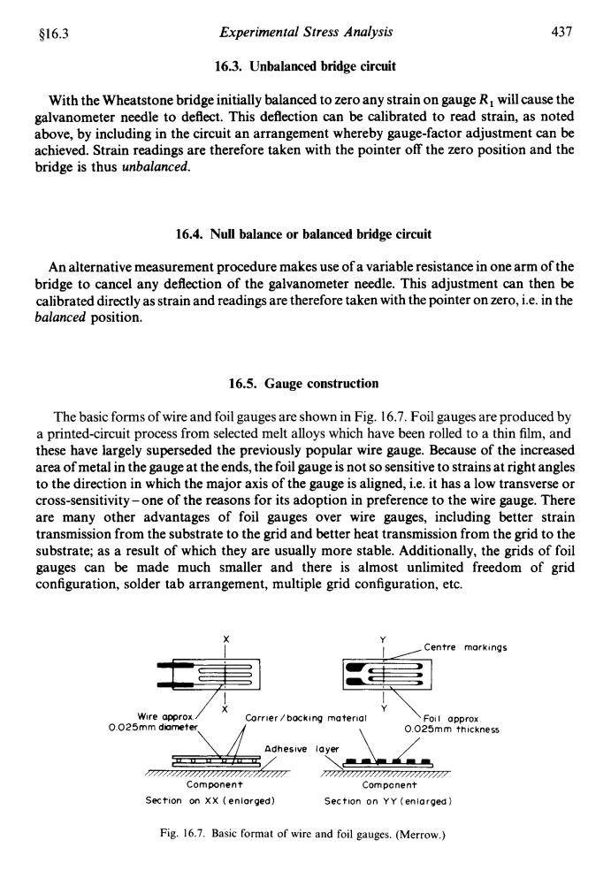
S16.3 Experimental Stress Analysis 437 16.3.Unbalanced bridge circuit With the Wheatstone bridge initially balanced to zero any strain on gauge R will cause the galvanometer needle to deflect.This deflection can be calibrated to read strain,as noted above,by including in the circuit an arrangement whereby gauge-factor adjustment can be achieved.Strain readings are therefore taken with the pointer off the zero position and the bridge is thus unbalanced. 16.4.Null balance or balanced bridge circuit An alternative measurement procedure makes use of a variable resistance in one arm of the bridge to cancel any deflection of the galvanometer needle.This adjustment can then be calibrated directly as strain and readings are therefore taken with the pointer on zero,i.e.in the balanced position. 16.5.Gauge construction The basic forms of wire and foil gauges are shown in Fig.16.7.Foil gauges are produced by a printed-circuit process from selected melt alloys which have been rolled to a thin film,and these have largely superseded the previously popular wire gauge.Because of the increased area of metal in the gauge at the ends,the foil gauge is not so sensitive to strains at right angles to the direction in which the major axis of the gauge is aligned,i.e.it has a low transverse or cross-sensitivity-one of the reasons for its adoption in preference to the wire gauge.There are many other advantages of foil gauges over wire gauges,including better strain transmission from the substrate to the grid and better heat transmission from the grid to the substrate;as a result of which they are usually more stable.Additionally,the grids of foil gauges can be made much smaller and there is almost unlimited freedom of grid configuration,solder tab arrangement,multiple grid configuration,etc. Centre morkings Wire approx. Corrier /backing materia Foil approx. O.025mm diameter 0.025mm thickness Adhesive layer 7P7777Z7 Component Compenent Section on XX (enlarged) Section on YY (enlarged) Fig.16.7.Basic format of wire and foil gauges.(Merrow.)
416.3 Experimental Stress Analysis 437 16.3. Unbalanced bridge circuit With the Wheatstone bridge initially balanced to zero any strain on gauge R, will cause the galvanometer needle to deflect. This deflection can be calibrated to read strain, as noted above, by including in the circuit an arrangement whereby gauge-factor adjustment can be achieved. Strain readings are therefore taken with the pointer off the zero position and the bridge is thus unbalanced. 16.4. Null balance or balanced bridge circuit An alternative measurement procedure makes use of a variable resistance in one arm of the bridge to cancel any deflection of the galvanometer needle. This adjustment can then be calibrated directly as strain and readings are therefore taken with the pointer on zero, i.e. in the balanced position. 16.5. Gauge construction The basic forms of wire and foil gauges are shown in Fig. 16.7. Foil gauges are produced by a printed-circuit process from selected melt alloys which have been rolled to a thin film, and these have largely superseded the previously popular wire gauge. Because of the increased area of metal in the gauge at the ends, the foil gauge is not so sensitive to strains at right angles to the direction in which the major axis of the gauge is aligned, i.e. it has a low transverse or cross-sensitivity -one of the reasons for its adoption in preference to the wire gauge. There are many other advantages of foil gauges over wire gauges, including better strain transmission from the substrate to the grid and better heat transmission from the grid to the substrate; as a result of which they are usually more stable. Additionally, the grids of foil gauges can be made much smaller and there is almost unlimited freedom of grid configuration, solder tab arrangement, multiple grid configuration, etc. X Y I ,Centre markings Y Wire approx / x Corrier/backing material 0 025rnm dometer. A \ 0 025mm thickness Component v Corn pcnent Section on XX (enlarged) Section on YY (enlarged) Fig. 16.7. Basic format of wire and foil gauges. (Merrow.)
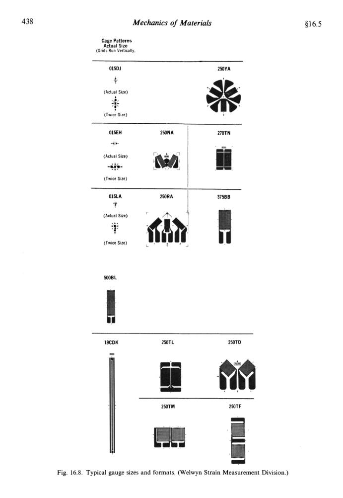
438 Mechanics of Materials S16.5 Gage Patterns Actual Size (Grids Run Vertically 015DJ 250YA (Actual Size) 年 米 (Twice Size)) 015EH 250NA 270TN 的 (Aclual Size) 冲 n 面 (Twice Size) 015LA 250RA 37588 (Actual Size) (Twice Size) 19CDK 250TL 250TD 250TM 250TF Fig.16.8.Typical gauge sizes and formats.(Welwyn Strain Measurement Division.)