Chapter 1 Introduction This chapter introduces the Cortex-M4 processor and instruction set,processor features and interfaces. configurable options,and product documentation. It ooo-12. 1.2 Featur on page 1-is s on page ARM100166000100en opygh1 nghts 1-11
Chapter 1 Introduction This chapter introduces the Cortex-M4 processor and instruction set, processor features and interfaces, configurable options, and product documentation. It contains the following sections: • 1.1 About the processor on page 1-12. • 1.2 Features on page 1-13. • 1.3 External interfaces on page 1-14. • 1.4 Configurable options on page 1-15. • 1.5 Product documentation on page 1-16. • 1.6 Product revisions on page 1-19. ARM 100166_0001_00_en Copyright © 2009, 2010, 2013, 2015 ARM. All rights reserved. 1-11 Non-Confidential

1.1 About the processor The Cortex-M4 processor is a low-power processor that features low gate count.low interupt latency. and low-cost debug The Cortex-M4 includes optional floating point arithmetic functionality.The processor is intended for deeply embedded applications that require fast interrupt response features. Related references Chapter 7 Floating-Point Unit on page 7-65. ARM100166_0001_00_en capyniwne209,2010,30m82915A5MAu7gsesened 1-12
1.1 About the processor The Cortex-M4 processor is a low-power processor that features low gate count, low interrupt latency, and low-cost debug. The Cortex-M4 includes optional floating point arithmetic functionality. The processor is intended for deeply embedded applications that require fast interrupt response features. Related references Chapter 7 Floating-Point Unit on page 7-65. 1 Introduction 1.1 About the processor ARM 100166_0001_00_en Copyright © 2009, 2010, 2013, 2015 ARM. All rights reserved. 1-12 Non-Confidential

12refeg 1.2 Features The Cortex-M4 processor incorporates a processor core,Nested Vectored Interrupt Controller(NVIC) high-performance bus interfaces,a low-cost debug solution.and an optional Floating Point Unit(FPU) The Cortex-M4 procesor incorporates the following features: A processor core A Nested Vectored Interrupt Controller(NVIC)closely integrated with the processor core to achieve interrupt processing h-performance bus interfac A low-cost d ug s on wi optional ability to Implement break patches mplement watc po ing,and system profiling Support printf()style debugging aoema Port Analy- (IP An option mory Protection PU) An optional Floating Point Unit (FPU) ARM100166000100en opygh1 nghts 1-13
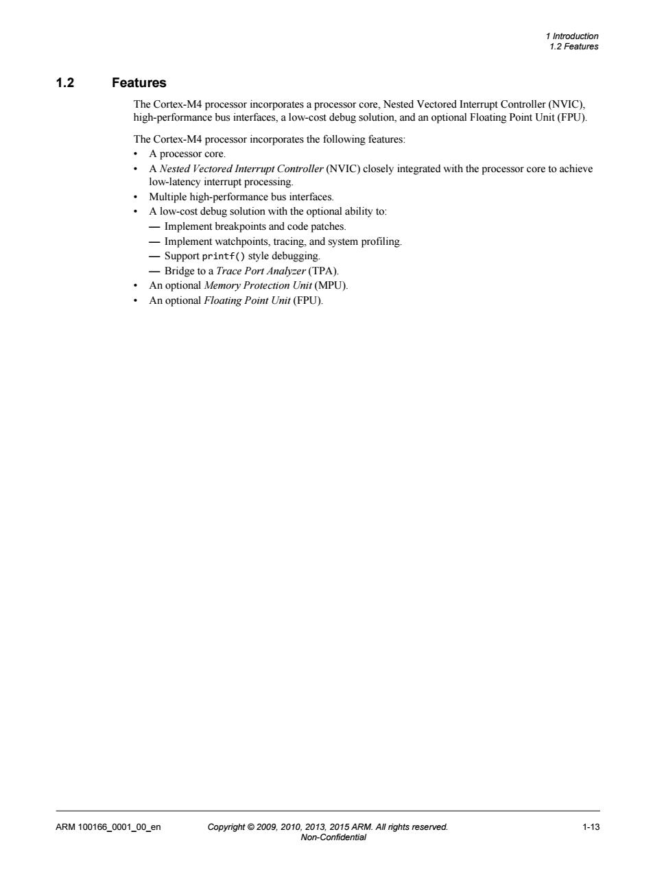
1.2 Features The Cortex-M4 processor incorporates a processor core, Nested Vectored Interrupt Controller (NVIC), high-performance bus interfaces, a low-cost debug solution, and an optional Floating Point Unit (FPU). The Cortex-M4 processor incorporates the following features: • A processor core. • A Nested Vectored Interrupt Controller (NVIC) closely integrated with the processor core to achieve low-latency interrupt processing. • Multiple high-performance bus interfaces. • A low-cost debug solution with the optional ability to: — Implement breakpoints and code patches. — Implement watchpoints, tracing, and system profiling. — Support printf() style debugging. — Bridge to a Trace Port Analyzer (TPA). • An optional Memory Protection Unit (MPU). • An optional Floating Point Unit (FPU). 1 Introduction 1.2 Features ARM 100166_0001_00_en Copyright © 2009, 2010, 2013, 2015 ARM. All rights reserved. 1-13 Non-Confidential

1.3 External interfaces The processor incorporates three exteral bus interfaces,an ETM interface that allows the connection of an Embedded Trace Macrocell,an AHB Trace Macrocell interface that enables simple connection of an ETM to the processor,and an Advanced High-performance Bus Access Port(AHB-AP)interface for debug accesses ocessor incorporates the following extemal interfaces interface Debug port interface ARM100166_0001_00_en copyniwne209,2010,30m82915An8MAw7osesened 1-14
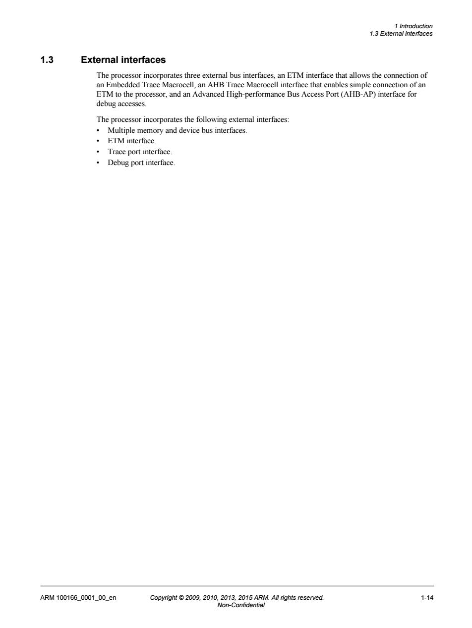
1.3 External interfaces The processor incorporates three external bus interfaces, an ETM interface that allows the connection of an Embedded Trace Macrocell, an AHB Trace Macrocell interface that enables simple connection of an ETM to the processor, and an Advanced High-performance Bus Access Port (AHB-AP) interface for debug accesses. The processor incorporates the following external interfaces: • Multiple memory and device bus interfaces. • ETM interface. • Trace port interface. • Debug port interface. 1 Introduction 1.3 External interfaces ARM 100166_0001_00_en Copyright © 2009, 2010, 2013, 2015 ARM. All rights reserved. 1-14 Non-Confidential

1.4 Configurable options 品 The following optional ents can be configured for the Cortex-M4 processor t(M Data Watch ce Un WT ace Macrocell (ETM).See the ETM-M4 Technical Reference Manual h-perf e B cess Port(AHB-AP). (HTM nit r (WIC) Bit-bandi Constant AHB control Note You can only configure trace functionality in the following combinations No trace functionality. ITM and DWT. ITM,DWT,and ETM. ·ITM,DWT,ETM,and HTM. You can configure the features provided in the DWT independently Related concepts 8.3 Flash Patch and Breakpoint Unit (FPB)on page 8-82 8.2 AHB-AP debug access port on page 8-79. 2.3.3 AHB Trace Macrocell interface on page 2-26. 6.1.2 Low power modes on page 6-62. 2.3.4 Debug Port AHB-AP interface on page 2-26. 3.7 Bit-banding on page 3-45. 2.3.1 Bus interfaces on page 2-24. Related references Chapter 5 Me i on page 5-57 Chapter 10 strumentation Trace Macrocell Unit on page -88 Chapter 11 Trace Port Interface Unit on page 11-92. Chapter 7 Floating-Point Unit on page 7-65. ARM100166000100en opygh1ghtsv 1-15
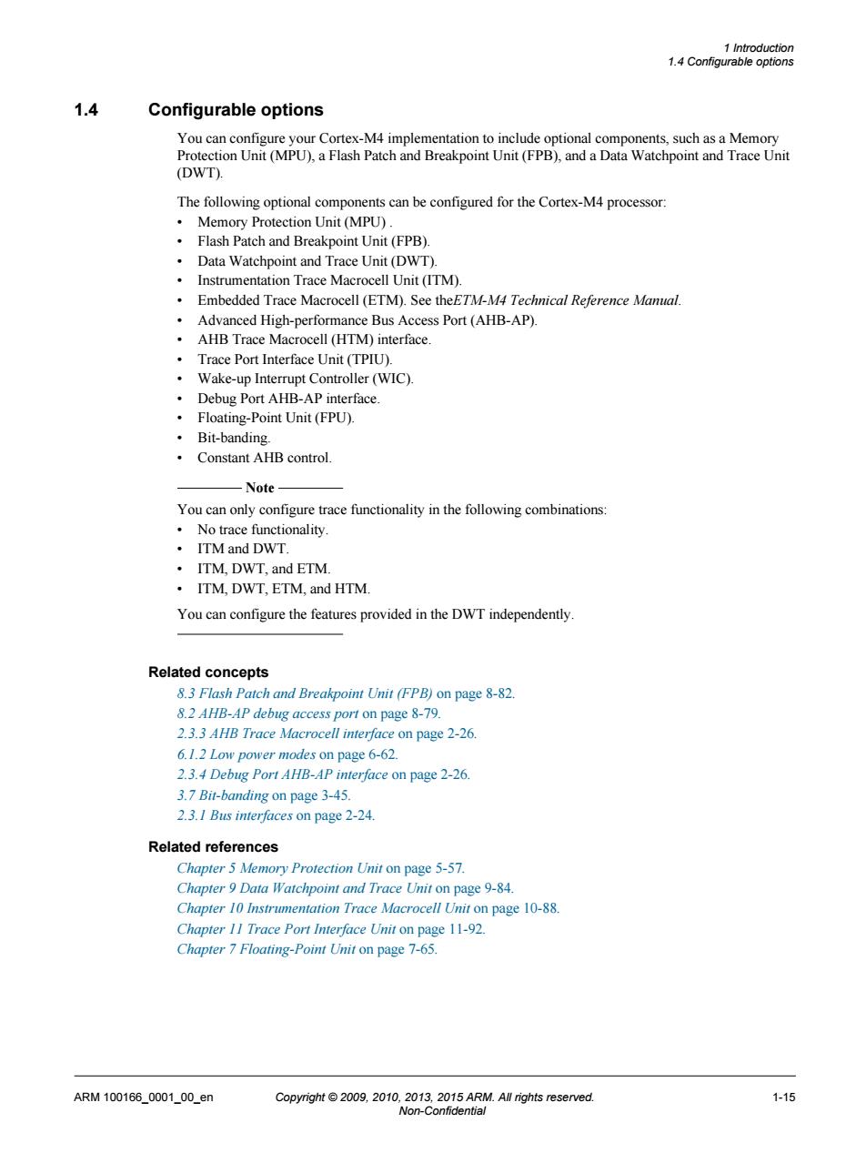
1.4 Configurable options You can configure your Cortex-M4 implementation to include optional components, such as a Memory Protection Unit (MPU), a Flash Patch and Breakpoint Unit (FPB), and a Data Watchpoint and Trace Unit (DWT). The following optional components can be configured for the Cortex-M4 processor: • Memory Protection Unit (MPU) . • Flash Patch and Breakpoint Unit (FPB). • Data Watchpoint and Trace Unit (DWT). • Instrumentation Trace Macrocell Unit (ITM). • Embedded Trace Macrocell (ETM). See theETM-M4 Technical Reference Manual. • Advanced High-performance Bus Access Port (AHB-AP). • AHB Trace Macrocell (HTM) interface. • Trace Port Interface Unit (TPIU). • Wake-up Interrupt Controller (WIC). • Debug Port AHB-AP interface. • Floating-Point Unit (FPU). • Bit-banding. • Constant AHB control. Note You can only configure trace functionality in the following combinations: • No trace functionality. • ITM and DWT. • ITM, DWT, and ETM. • ITM, DWT, ETM, and HTM. You can configure the features provided in the DWT independently. Related concepts 8.3 Flash Patch and Breakpoint Unit (FPB) on page 8-82. 8.2 AHB-AP debug access port on page 8-79. 2.3.3 AHB Trace Macrocell interface on page 2-26. 6.1.2 Low power modes on page 6-62. 2.3.4 Debug Port AHB-AP interface on page 2-26. 3.7 Bit-banding on page 3-45. 2.3.1 Bus interfaces on page 2-24. Related references Chapter 5 Memory Protection Unit on page 5-57. Chapter 9 Data Watchpoint and Trace Unit on page 9-84. Chapter 10 Instrumentation Trace Macrocell Unit on page 10-88. Chapter 11 Trace Port Interface Unit on page 11-92. Chapter 7 Floating-Point Unit on page 7-65. 1 Introduction 1.4 Configurable options ARM 100166_0001_00_en Copyright © 2009, 2010, 2013, 2015 ARM. All rights reserved. 1-15 Non-Confidential