SI STM32L431xx ife.augmented Ultra-low-power ArmR CortexR-M4 32-bit MCU+FPU,100DMIPS up to 256KB Flash,64KB SRAM,analog,audio Datasheet-production data Features .Ultra-low-power with FlexPowerControl 巴 1.71 V to 3.6 V power supply -40℃to85/105/125℃te 8品岛3 Up to 83 fast l/Os,most 5 V-tolerant RTC with HW calendar,alarms and calibration 8 nA Shutdown mode(5 wakeup pins) -28 nA Standby mode(5 wakeup pins) nsors -280 nA Standby mode with RTC M92eae1a8AwhRc 1mers:i advanced motor-contro bit basic,2x low-power 16-bit timers (available Batch acquisition mode (BAM) in Stop mode).2x watchdogs.SysTick timer 4 us wak eup from Stop mode ·Memories Brown out res t(BOR) -Up to 256 KB single bank Flash, nierconectmatn readout protection FPU. 64KBoeoatvch Quad SPI memory interface Rich an ction Performance benchmark 1.25 DMIPS/MHz(Drystone 2.1) CoreMark(3.42 CoreMark/MHz 2x 12-bit DAC output channels,low-power sample and hold 1x operational amplifier with built-in PGA 2x ultra-low-power comparators 16x communication interfaces Clock Sources -1x SAl (serial audio interface) 4 to 48 MHz crystal oscillator 3x 12C FM+(1 Mbit/s).SMBus/PMBus 32 kHz crystal oscillator for RTC(LSE) 4x USARTs (ISO 7816.LIN.IrDA,modem) Internal 16 MHz factory-trimmed RC(1%) 1x LPUART(Stop 2 wake-up) nternal low-power 32 kHz RC (+5%) 3x SPls (and 1x Quad SPI) ed 100( CAN(2.0B Active)and SDMMC inte than ce Internal 48 MHz with clock recovery .14-channel DMA controller -2 PLLs for system clock,audio.ADC True random number generator .CRC calculation unit,96-bit unique ID May 2018 DS11453 Rev 3 1/208 is is information on a product in full productio www.st.com
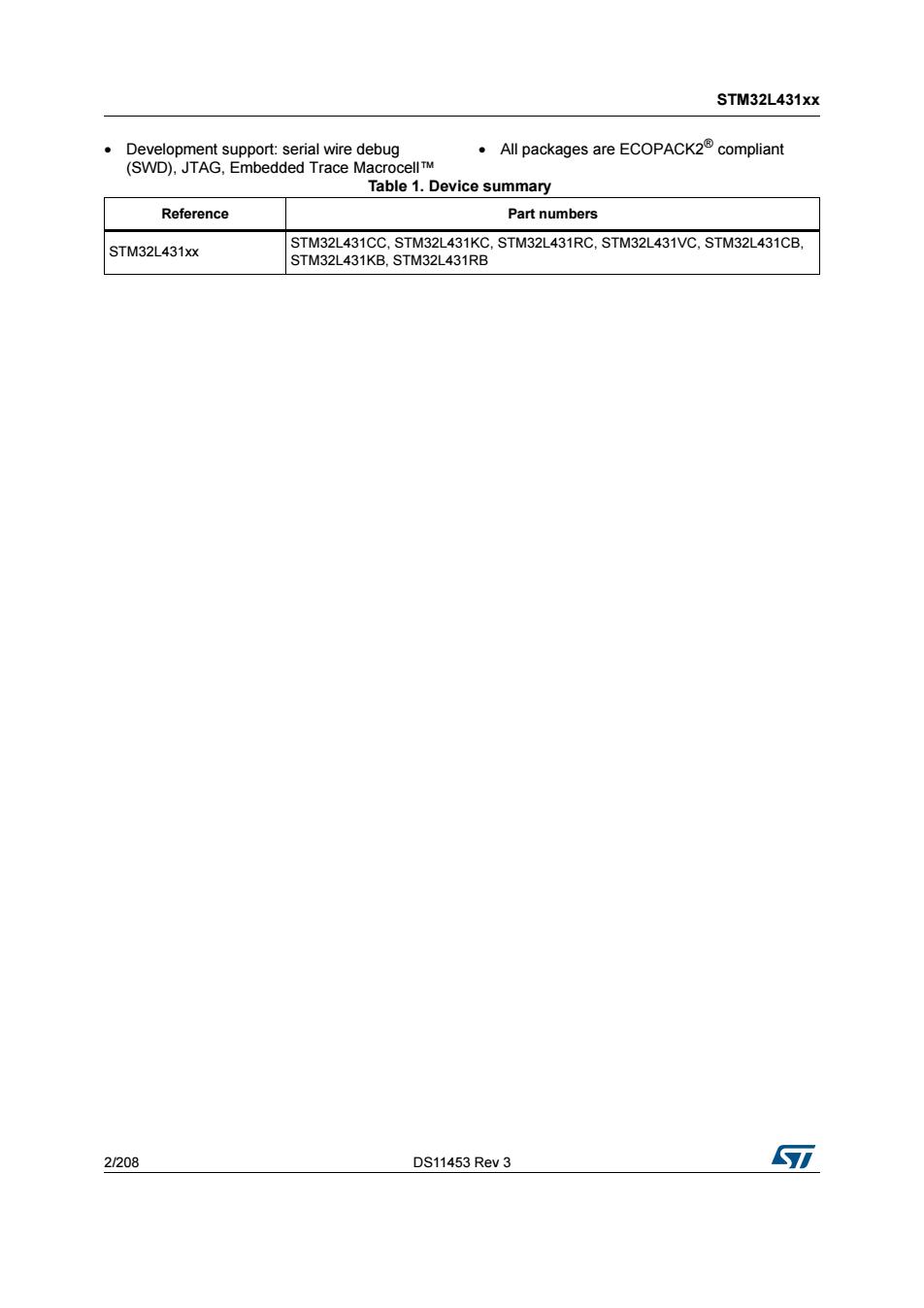
This is information on a product in full production. May 2018 DS11453 Rev 3 1/208 STM32L431xx Ultra-low-power Arm® Cortex®-M4 32-bit MCU+FPU, 100DMIPS, up to 256KB Flash, 64KB SRAM, analog, audio Datasheet - production data Features • Ultra-low-power with FlexPowerControl – 1.71 V to 3.6 V power supply – -40 °C to 85/105/125 °C temperature range – 200 nA in VBAT mode: supply for RTC and 32x32-bit backup registers – 8 nA Shutdown mode (5 wakeup pins) – 28 nA Standby mode (5 wakeup pins) – 280 nA Standby mode with RTC – 1.0 µA Stop 2 mode, 1.28 µA with RTC – 84 µA/MHz run mode – Batch acquisition mode (BAM) – 4 µs wakeup from Stop mode – Brown out reset (BOR) – Interconnect matrix • Core: Arm® 32-bit Cortex®-M4 CPU with FPU, Adaptive real-time accelerator (ART Accelerator™) allowing 0-wait-state execution from Flash memory, frequency up to 80 MHz, MPU, 100DMIPS and DSP instructions • Performance benchmark – 1.25 DMIPS/MHz (Drystone 2.1) – 273.55 CoreMark® (3.42 CoreMark/MHz @ 80 MHz) • Energy benchmark – 176.7 ULPBench® score • Clock Sources – 4 to 48 MHz crystal oscillator – 32 kHz crystal oscillator for RTC (LSE) – Internal 16 MHz factory-trimmed RC (±1%) – Internal low-power 32 kHz RC (±5%) – Internal multispeed 100 kHz to 48 MHz oscillator, auto-trimmed by LSE (better than ±0.25 % accuracy) – Internal 48 MHz with clock recovery – 2 PLLs for system clock, audio, ADC • Up to 83 fast I/Os, most 5 V-tolerant • RTC with HW calendar, alarms and calibration • Up to 21 capacitive sensing channels: support touchkey, linear and rotary touch sensors • 11x timers: 1x 16-bit advanced motor-control, 1x 32-bit and 2x 16-bit general purpose, 2x 16- bit basic, 2x low-power 16-bit timers (available in Stop mode), 2x watchdogs, SysTick timer • Memories – Up to 256 KB single bank Flash, proprietary code readout protection – 64 KB of SRAM including 16 KB with hardware parity check – Quad SPI memory interface • Rich analog peripherals (independent supply) – 1x 12-bit ADC 5 Msps, up to 16-bit with hardware oversampling, 200 µA/Msps – 2x 12-bit DAC output channels, low-power sample and hold – 1x operational amplifier with built-in PGA – 2x ultra-low-power comparators • 16x communication interfaces – 1x SAI (serial audio interface) – 3x I2C FM+(1 Mbit/s), SMBus/PMBus – 4x USARTs (ISO 7816, LIN, IrDA, modem) – 1x LPUART (Stop 2 wake-up) – 3x SPIs (and 1x Quad SPI) – CAN (2.0B Active) and SDMMC interface – SWPMI single wire protocol master I/F – IRTIM (Infrared interface) • 14-channel DMA controller • True random number generator • CRC calculation unit, 96-bit unique ID LQFP64 (10x10) UFBGA100 (7×7) LQFP48 (7x7) UFBGA64 (5x5) LQFP100 (14x14) UFQFPN32 (5x5) WLCSP64 UFQFPN48 (7x7) WLCSP49 www.st.com
STM32L431xx beXebPTaspPoetseeie All packages are ECOPACK2compliant cell T Table 1.Device summary Reference Part numbers STM32L431xx C.STM32L431RC.STM32L431VC,STM32L431CB, 2208 DS11453 Rev 3 7
STM32L431xx 2/208 DS11453 Rev 3 • Development support: serial wire debug (SWD), JTAG, Embedded Trace Macrocell™ • All packages are ECOPACK2® compliant Table 1. Device summary Reference Part numbers STM32L431xx STM32L431CC, STM32L431KC, STM32L431RC, STM32L431VC, STM32L431CB, STM32L431KB, STM32L431RB
STM32L431xx Contents Contents Introduction.....................12 Description. ,13 Functional overview 17 3.1 Arm Cortex-M4 core with FPU............................... 1> 3.2 Adaptive real-time memory accelerator(ART AcceleratorTM).........17 3.3 Memory protection unit....................................17 3.4 Embedded Flash memory 3.5 Embedded SRAM ..19 3.6 Firewall..............19 3.7 Boot modes 20 3.8 Cyclic redundancy check calculation unit(CRC) .20 3.9 Power supply management 3.9.1 Power supply schemes 20 3.92 Power supply supervisor 22 3.9.3 Voltage regulator..........................................23 3.9.4 Low-power modes .23 3.9.5 Resetmode..................................... 3 3.9.6 VBAT operation 3 3.10 Interconnect matrix..................................... …3 3.11 Clocks and startup..........................................33 3.12 General-purpose inputs/outputs(GPIOs).............. .36 3.13 Direct memory access controller(DMA) .36 3.14 Interrupts and events 37 3.14.1 Nested vectored interrupt controller(NVIC) 3.14.2 Extended interrupt/event controller(EXTI) .37 3.15 Analog to digital converter (ADC)...............................38 3151 Temperature sensor. ,..38 3.15.2 Internal voltage reference(VREFINT) 39 3.15.3 VBAT battery voltage monitoring .39 3.16 Digital to analog converter(DAC) 39 7 DS11453 Rev 3 3/208
DS11453 Rev 3 3/208 STM32L431xx Contents 6 Contents 1 Introduction . . . . . . . . . . . . . . . . . . . . . . . . . . . . . . . . . . . . . . . . . . . . . . . 12 2 Description . . . . . . . . . . . . . . . . . . . . . . . . . . . . . . . . . . . . . . . . . . . . . . . . 13 3 Functional overview . . . . . . . . . . . . . . . . . . . . . . . . . . . . . . . . . . . . . . . . 17 3.1 Arm® Cortex®-M4 core with FPU . . . . . . . . . . . . . . . . . . . . . . . . . . . . . . . 17 3.2 Adaptive real-time memory accelerator (ART Accelerator™) . . . . . . . . . 17 3.3 Memory protection unit . . . . . . . . . . . . . . . . . . . . . . . . . . . . . . . . . . . . . . . 17 3.4 Embedded Flash memory . . . . . . . . . . . . . . . . . . . . . . . . . . . . . . . . . . . . 18 3.5 Embedded SRAM . . . . . . . . . . . . . . . . . . . . . . . . . . . . . . . . . . . . . . . . . . . 19 3.6 Firewall . . . . . . . . . . . . . . . . . . . . . . . . . . . . . . . . . . . . . . . . . . . . . . . . . . . 19 3.7 Boot modes . . . . . . . . . . . . . . . . . . . . . . . . . . . . . . . . . . . . . . . . . . . . . . . 20 3.8 Cyclic redundancy check calculation unit (CRC) . . . . . . . . . . . . . . . . . . . 20 3.9 Power supply management . . . . . . . . . . . . . . . . . . . . . . . . . . . . . . . . . . . 20 3.9.1 Power supply schemes . . . . . . . . . . . . . . . . . . . . . . . . . . . . . . . . . . . . . 20 3.9.2 Power supply supervisor . . . . . . . . . . . . . . . . . . . . . . . . . . . . . . . . . . . . 22 3.9.3 Voltage regulator . . . . . . . . . . . . . . . . . . . . . . . . . . . . . . . . . . . . . . . . . . 23 3.9.4 Low-power modes . . . . . . . . . . . . . . . . . . . . . . . . . . . . . . . . . . . . . . . . . 23 3.9.5 Reset mode . . . . . . . . . . . . . . . . . . . . . . . . . . . . . . . . . . . . . . . . . . . . . . 31 3.9.6 VBAT operation . . . . . . . . . . . . . . . . . . . . . . . . . . . . . . . . . . . . . . . . . . . 31 3.10 Interconnect matrix . . . . . . . . . . . . . . . . . . . . . . . . . . . . . . . . . . . . . . . . . . 31 3.11 Clocks and startup . . . . . . . . . . . . . . . . . . . . . . . . . . . . . . . . . . . . . . . . . . 33 3.12 General-purpose inputs/outputs (GPIOs) . . . . . . . . . . . . . . . . . . . . . . . . . 36 3.13 Direct memory access controller (DMA) . . . . . . . . . . . . . . . . . . . . . . . . . . 36 3.14 Interrupts and events . . . . . . . . . . . . . . . . . . . . . . . . . . . . . . . . . . . . . . . . 37 3.14.1 Nested vectored interrupt controller (NVIC) . . . . . . . . . . . . . . . . . . . . . . 37 3.14.2 Extended interrupt/event controller (EXTI) . . . . . . . . . . . . . . . . . . . . . . 37 3.15 Analog to digital converter (ADC) . . . . . . . . . . . . . . . . . . . . . . . . . . . . . . . 38 3.15.1 Temperature sensor . . . . . . . . . . . . . . . . . . . . . . . . . . . . . . . . . . . . . . . . 38 3.15.2 Internal voltage reference (VREFINT) . . . . . . . . . . . . . . . . . . . . . . . . . . 39 3.15.3 VBAT battery voltage monitoring . . . . . . . . . . . . . . . . . . . . . . . . . . . . . . 39 3.16 Digital to analog converter (DAC) . . . . . . . . . . . . . . . . . . . . . . . . . . . . . . . 39
Contents STM32L431xx 3.17 Voltage reference buffer(VREFBUF) 40 3.18 Comparators(COMP)... ..41 3.19 Operational amplifier(OPAMP) 3.20 Touch sensing controller(TSC) 41 3.21 Random number generator(RNG) …42 3.22 Timers and watchdogs........................................42 3.22.1 Advanced-control timer(TIM1) 43 322.2 General-purpose timers (TIM2.TIM15,TIM16) 44 3.22.3 Basic timers (TIM6 and TIM7) 8 3224 Low-power timer(LPTIM1 and LPTIM2) 3.22.5 Infrared interface (IRTIM 3.22.6 Independent watchdog (IWDG)... .45 3227 System window watchdog (WDG) 3.22.8 SysTick timer..... .45 3.23 Real-time clock(RTC)and backup registers 46 3.24 Inter-integrated circuit interface (IC)...... .47 3.25 Universal synchronous/asynchronous receiver transmitter(USART)...48 3.26 Low-power universal asynchronous receiver transmitter(LPUART) 3.27 Serial peripheral interface(SPI) .50 3.28 Serial audio interfaces(SAI)................................... % 3.29 Single wire protocol master interface(SWPMI) 1 3.30 Controller area network(CAN).. .51 3.31 Secure digital input/output and MultiMediaCards Interface(SDMMC)...52 3.32 Clock recovery system(CRS) 52 3.33 Quad SPI memory interface(QUADSPI) .53 3.34 Development support.............. ..54 3.34.1 Serial wire JTAG debug port (SWJ-DP) ...54 3.342 Embedded Trace MacrocellT 54 4 Pinouts and pin description...................................55 Memory mapping ,80 6 Electrical characteristics ...84 61 Parameter conditions 84 4208 DS11453 Rev 3 7
Contents STM32L431xx 4/208 DS11453 Rev 3 3.17 Voltage reference buffer (VREFBUF) . . . . . . . . . . . . . . . . . . . . . . . . . . . . 40 3.18 Comparators (COMP) . . . . . . . . . . . . . . . . . . . . . . . . . . . . . . . . . . . . . . . 41 3.19 Operational amplifier (OPAMP) . . . . . . . . . . . . . . . . . . . . . . . . . . . . . . . . 41 3.20 Touch sensing controller (TSC) . . . . . . . . . . . . . . . . . . . . . . . . . . . . . . . . 41 3.21 Random number generator (RNG) . . . . . . . . . . . . . . . . . . . . . . . . . . . . . . 42 3.22 Timers and watchdogs . . . . . . . . . . . . . . . . . . . . . . . . . . . . . . . . . . . . . . . 42 3.22.1 Advanced-control timer (TIM1) . . . . . . . . . . . . . . . . . . . . . . . . . . . . . . . 43 3.22.2 General-purpose timers (TIM2, TIM15, TIM16) . . . . . . . . . . . . . . . . . . . 44 3.22.3 Basic timers (TIM6 and TIM7) . . . . . . . . . . . . . . . . . . . . . . . . . . . . . . . . 44 3.22.4 Low-power timer (LPTIM1 and LPTIM2) . . . . . . . . . . . . . . . . . . . . . . . . 44 3.22.5 Infrared interface (IRTIM) . . . . . . . . . . . . . . . . . . . . . . . . . . . . . . . . . . . 45 3.22.6 Independent watchdog (IWDG) . . . . . . . . . . . . . . . . . . . . . . . . . . . . . . . 45 3.22.7 System window watchdog (WWDG) . . . . . . . . . . . . . . . . . . . . . . . . . . . 45 3.22.8 SysTick timer . . . . . . . . . . . . . . . . . . . . . . . . . . . . . . . . . . . . . . . . . . . . . 45 3.23 Real-time clock (RTC) and backup registers . . . . . . . . . . . . . . . . . . . . . . 46 3.24 Inter-integrated circuit interface (I2C) . . . . . . . . . . . . . . . . . . . . . . . . . . . . 47 3.25 Universal synchronous/asynchronous receiver transmitter (USART) . . . 48 3.26 Low-power universal asynchronous receiver transmitter (LPUART) . . . . 49 3.27 Serial peripheral interface (SPI) . . . . . . . . . . . . . . . . . . . . . . . . . . . . . . . . 50 3.28 Serial audio interfaces (SAI) . . . . . . . . . . . . . . . . . . . . . . . . . . . . . . . . . . . 50 3.29 Single wire protocol master interface (SWPMI) . . . . . . . . . . . . . . . . . . . . 51 3.30 Controller area network (CAN) . . . . . . . . . . . . . . . . . . . . . . . . . . . . . . . . . 51 3.31 Secure digital input/output and MultiMediaCards Interface (SDMMC) . . . 52 3.32 Clock recovery system (CRS) . . . . . . . . . . . . . . . . . . . . . . . . . . . . . . . . . 52 3.33 Quad SPI memory interface (QUADSPI) . . . . . . . . . . . . . . . . . . . . . . . . . 53 3.34 Development support . . . . . . . . . . . . . . . . . . . . . . . . . . . . . . . . . . . . . . . . 54 3.34.1 Serial wire JTAG debug port (SWJ-DP) . . . . . . . . . . . . . . . . . . . . . . . . . 54 3.34.2 Embedded Trace Macrocell™ . . . . . . . . . . . . . . . . . . . . . . . . . . . . . . . . 54 4 Pinouts and pin description . . . . . . . . . . . . . . . . . . . . . . . . . . . . . . . . . . 55 5 Memory mapping . . . . . . . . . . . . . . . . . . . . . . . . . . . . . . . . . . . . . . . . . . . 80 6 Electrical characteristics . . . . . . . . . . . . . . . . . . . . . . . . . . . . . . . . . . . . 84 6.1 Parameter conditions . . . . . . . . . . . . . . . . . . . . . . . . . . . . . . . . . . . . . . . . 84
STM32L431xx Contents Minimum and maximum values 84 612 Typical values 6.1.3 Typical curves 84 614 Loading capacitor 61.5 Pin input voltage 「 6.1.6 Power supply scheme 85 6.1.7 Current consumption measurement 6.2 Absolute maximum ratings 86 6.3 Operating conditions................................... % 6.3.1 General operating conditions 632 Operating conditions at power-up power-down................. 9 6.3.3 Embedded reset and power control block characteristics9 63.4 Embedded voltage reference 6.3.5 Supply current characteristics................................ 93 6.3.6 Wakeup time from low-power modes and voltage scaling transition times......................... ....111 6.3.7 External clock source characteristics .114 63.8 nteral clock source characteristics 119 6.3.9 PLL characteristics,...。.,.,.,,.,,,..,..,.,,,,., 125 6.3.10 Flash memory characteristics 127 6.3.11 EMC characteristics.............,,.,.................. 128 6.312 Electrical sensitivity characteristics 129 63.13 current injection characteristics 130 6.3.14 lo port characteristics.....................................131 6.3.15 NRST pin characteristics ,136 63.16 Extended interrupt and event controller input(EXTI)characteristics 137 6.3.17 Analoa switches booster ,137 6.3.18 6.3.19 Digital-to-Analog converter characteristics .151 6.3.20 Voltage reference buffer characteristics 1 6.3.21 Comparator characteristics 15 6.3.22 Operational amplifiers characteristics 5 6.3.23 Temperature sensor characteristics 6 6.324 VBAr monitoring characteristics 6.3.25 Timer characteristics 163 6.3.26 Communication interfaces characteristics 164 DS11453 Rev 3 5/208
DS11453 Rev 3 5/208 STM32L431xx Contents 6 6.1.1 Minimum and maximum values . . . . . . . . . . . . . . . . . . . . . . . . . . . . . . . 84 6.1.2 Typical values . . . . . . . . . . . . . . . . . . . . . . . . . . . . . . . . . . . . . . . . . . . . 84 6.1.3 Typical curves . . . . . . . . . . . . . . . . . . . . . . . . . . . . . . . . . . . . . . . . . . . . 84 6.1.4 Loading capacitor . . . . . . . . . . . . . . . . . . . . . . . . . . . . . . . . . . . . . . . . . 84 6.1.5 Pin input voltage . . . . . . . . . . . . . . . . . . . . . . . . . . . . . . . . . . . . . . . . . . 84 6.1.6 Power supply scheme . . . . . . . . . . . . . . . . . . . . . . . . . . . . . . . . . . . . . . 85 6.1.7 Current consumption measurement . . . . . . . . . . . . . . . . . . . . . . . . . . . 86 6.2 Absolute maximum ratings . . . . . . . . . . . . . . . . . . . . . . . . . . . . . . . . . . . . 86 6.3 Operating conditions . . . . . . . . . . . . . . . . . . . . . . . . . . . . . . . . . . . . . . . . 88 6.3.1 General operating conditions . . . . . . . . . . . . . . . . . . . . . . . . . . . . . . . . . 88 6.3.2 Operating conditions at power-up / power-down . . . . . . . . . . . . . . . . . . 89 6.3.3 Embedded reset and power control block characteristics . . . . . . . . . . . 89 6.3.4 Embedded voltage reference . . . . . . . . . . . . . . . . . . . . . . . . . . . . . . . . . 91 6.3.5 Supply current characteristics . . . . . . . . . . . . . . . . . . . . . . . . . . . . . . . . 93 6.3.6 Wakeup time from low-power modes and voltage scaling transition times . . . . . . . . . . . . . . . . . . . . . . . . . . . . . . . . . . . . . . . . . . . 111 6.3.7 External clock source characteristics . . . . . . . . . . . . . . . . . . . . . . . . . . 114 6.3.8 Internal clock source characteristics . . . . . . . . . . . . . . . . . . . . . . . . . . 119 6.3.9 PLL characteristics . . . . . . . . . . . . . . . . . . . . . . . . . . . . . . . . . . . . . . . . 125 6.3.10 Flash memory characteristics . . . . . . . . . . . . . . . . . . . . . . . . . . . . . . . 127 6.3.11 EMC characteristics . . . . . . . . . . . . . . . . . . . . . . . . . . . . . . . . . . . . . . . 128 6.3.12 Electrical sensitivity characteristics . . . . . . . . . . . . . . . . . . . . . . . . . . . 129 6.3.13 I/O current injection characteristics . . . . . . . . . . . . . . . . . . . . . . . . . . . 130 6.3.14 I/O port characteristics . . . . . . . . . . . . . . . . . . . . . . . . . . . . . . . . . . . . . 131 6.3.15 NRST pin characteristics . . . . . . . . . . . . . . . . . . . . . . . . . . . . . . . . . . . 136 6.3.16 Extended interrupt and event controller input (EXTI) characteristics . . 137 6.3.17 Analog switches booster . . . . . . . . . . . . . . . . . . . . . . . . . . . . . . . . . . . 137 6.3.18 Analog-to-Digital converter characteristics . . . . . . . . . . . . . . . . . . . . . 138 6.3.19 Digital-to-Analog converter characteristics . . . . . . . . . . . . . . . . . . . . . 151 6.3.20 Voltage reference buffer characteristics . . . . . . . . . . . . . . . . . . . . . . . 156 6.3.21 Comparator characteristics . . . . . . . . . . . . . . . . . . . . . . . . . . . . . . . . . 158 6.3.22 Operational amplifiers characteristics . . . . . . . . . . . . . . . . . . . . . . . . . 159 6.3.23 Temperature sensor characteristics . . . . . . . . . . . . . . . . . . . . . . . . . . . 162 6.3.24 VBAT monitoring characteristics . . . . . . . . . . . . . . . . . . . . . . . . . . . . . . 163 6.3.25 Timer characteristics . . . . . . . . . . . . . . . . . . . . . . . . . . . . . . . . . . . . . . 163 6.3.26 Communication interfaces characteristics . . . . . . . . . . . . . . . . . . . . . . 164