
$8.4 Torsion 181 or,in terms of some internal radius r, G0 -LI-GY (8.10) These equations indicate that the shear stress and shear strain vary linearly with radius and have their maximum value at the outside radius(Fig.8.4).The applied shear stresses in the plane of the cross-section are accompanied by complementary stresses of equal value on longitudinal planes as indicated in Figs.8.1 and 8.4.The significance of these longitudinal shears to material failure is discussed further in $8.10. Complementary longitudinal shears Fig.8.4.Complementary longitudinal shear stress in a shaft subjected to torsion. 8.4.Section modulus It is sometimes convenient to re-write part of the torsion theory formula to obtain the maximum shear stress in shafts as follows: Tt 万=R TR With R the outside radius of the shaft the above equation yields the greatest value possible for t (Fig.8.4), TR i.e. Tmax= tmu-Z (8.11) where Z =J/R is termed the polar section modulus.It will be seen from the preceding section that: πD3 for solid shafts, Z= (8.12) 16 and for hollow shafts, z=0*-d4 (8.13) 16D
$8.4 Torsion 181 or, in terms of some internal radius r, (8.10) These equations indicate that the shear stress and shear strain vary linearly with radius and have their maximum value at the outside radius (Fig. 8.4). The applied shear stresses in the plane of the cross-section are accompanied by complementary stresses of equal value on longitudinal planes as indicated in Figs. 8.1 and 8.4. The significance of these longitudinal shears to material failure is discussed further in 88.10. Fig. 8.4. Complementary longitudinal shear stress in a shaft subjected to torsion. 8.4. Section modulus It is sometimes convenient to re-write part of the torsion theory formula to obtain the maximum shear stress in shafts as follows: TT JR -=- With R the outside radius of the shaft the above equation yields the greatest value possible for T (Fig. 8.4), i.e. TR 7-= - J T Z .. T-=- (8.11) where 2 = J/R is termed the polar section modulus. It will be seen from the preceding section that: nD3 16 for solid shafts, Z=- (8.12) and for hollow shafts, ~(D1-d~) 160 Z- (8.13)
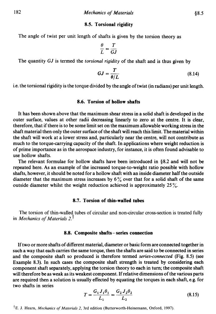
182 Mechanics of Materials §8.5 8.5.Torsional rigidity The angle of twist per unit length of shafts is given by the torsion theory as 6 T L"G可 The quantity GJ is termed the torsional rigidity of the shaft and is thus given by GJ=T 0/L (8.14) i.e.the torsional rigidity is the torque divided by the angle of twist(in radians)per unit length. 8.6.Torsion of hollow shafts It has been shown above that the maximum shear stress in a solid shaft is developed in the outer surface,values at other radii decreasing linearly to zero at the centre.It is clear, therefore,that if there is to be some limit set on the maximum allowable working stress in the shaft material then only the outer surface of the shaft will reach this limit.The material within the shaft will work at a lower stress and,particularly near the centre,will not contribute as much to the torque-carrying capacity of the shaft.In applications where weight reduction is of prime importance as in the aerospace industry,for instance,it is often found advisable to use hollow shafts. The relevant formulae for hollow shafts have been introduced in $8.2 and will not be repeated here.As an example of the increased torque-to-weight ratio possible with hollow shafts,however,it should be noted for a hollow shaft with an inside diameter half the outside diameter that the maximum stress increases by 6%over that for a solid shaft of the same outside diameter whilst the weight reduction achieved is approximately 25 8.7.Torsion of thin-walled tubes The torsion of thin-walled tubes of circular and non-circular cross-section is treated fully in Mechanics of Materials 2. 8.8.Composite shafts-series connection If two or more shafts of different material,diameter or basic form are connected together in such a way that each carries the same torque,then the shafts are said to be connected in series and the composite shaft so produced is therefore termed series-connected (Fig.8.5)(see Example 8.3).In such cases the composite shaft strength is treated by considering each component shaft separately,applying the torsion theory to each in turn;the composite shaft will therefore be as weak as its weakest component.If relative dimensions of the various parts are required then a solution is usually effected by equating the torques in each shaft,e.g.for two shafts in series T=C1J8=G2J202 (8.15) L2 1E.J.Hearn,Mechanics of Materials 2,3rd edition(Butterworth-Heinemann,Oxford,1997)
182 Mechanics of Materials $8.5 8.5. Torsional rigidity The angle of twist per unit length of shafts is given by the torsion theory as e~ L=GJ - The quantity GJ is termed the torsional rigidity of the shaft and is thus given by T GJ =- 91~ (8.14) i.e. the torsional rigidity is the torque divided by the angle of twist (in radians) per unit length. 8.6. Torsion of hollow shafts It has been shown above that the maximum shear stress in a solid shaft is developed in the outer surface, values at other radii decreasing linearly to zero at the centre. It is clear, therefore, that if there is to be some limit set on the maximum allowable working stress in the shaft material then only the outer surface of the shaft will reach this limit. The material within the shaft will work at a lower stress and, particularly near the centre, will not contribute as much to the torque-carrying capacity of the shaft. In applications where weight reduction is of prime importance as in the aerospace industry, for instance, it is often found advisable to use hollow shafts. The relevant formulae for hollow shafts have been introduced in $8.2 and will not be repeated here. As an example of the increased torque-to-weight ratio possible with hollow shafts, however, it should be noted for a hollow shaft with an inside diameter half the outside diameter that the maximum stress increases by 6 % over that for a solid shaft of the same outside diameter whilst the weight reduction achieved is approximately 25 %. 8.7. Torsion of thin-walled tubes The torsion of thin-walled tubes of circular and non-circular cross-section is treated fully in Mechanics of Materials 2. t 8.8. Composite shafts - series connection If two or more shafts of different material, diameter or basic form are connected together in such a way that each carries the same torque, then the shafts are said to be connected in series and the composite shaft so produced is therefore termed series-connected (Fig. 8.5) (see Example 8.3). In such cases the composite shaft strength is treated by considering each component shaft separately, applying the torsion theory to each in turn; the composite shaft will therefore be as weak as its weakest component. If relative dimensions of the various parts are required then a solution is usually effected by equating the torques in each shaft, e.g. for two shafts in series T=----- GlJlO1 =- Ll L2 t E. J. Hearn, Mechanics of Materials 2, 3rd edition (Butterworth-Heinemann, Oxford, 1997). (8.15)
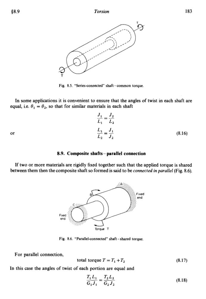
$8.9 Torsion 183 Fig.8.5."Series-connected"shaft-common torque. In some applications it is convenient to ensure that the angles of twist in each shaft are equal,i.e.0 =02,so that for similar materials in each shaft J1=J2 Ly L2 or =4 LJ (8.16 8.9.Composite shafts-parallel connection If two or more materials are rigidly fixed together such that the applied torque is shared between them then the composite shaft so formed is said to be connected in parallel (Fig.8.6). Fixed end end Torque T Fig.8.6."Parallel-connected"shaft-shared torque. For parallel connection, total torque T=T1+T2 (8.17) In this case the angles of twist of each portion are equal and TiL:T2L2 三 (8.18) G1J1G2J2
58.9 Torsion T 183 Fig. 8.5. “Series<onnected shaft - common torque. In some applications it is convenient to ensure that the angles of twist in each shaft are equal, i.e. 8, = f12, so that for similar materials in each shaft Jl Jz Ll L2 LZ J2 --_ - - Ll =- J1 or (8.16) 8.9. Composite shafts - parallel connection If two or more materials are rigidly fixed together such that the applied torque is shared between them then the composite shaft so formed is said to be connected in parallel (Fig. 8.6). Torque T Fig. 8.6. “Parallelconnected” shaft - shared torque. For parallel connection, total torque T = TI +Tz In this case the angles of twist of each portion are equal and (8.17) (8.18)