§6.1.1 Block Diagram Representation For the implementation of an LTI digital filter, the input-output relationship must be described by a valid computational algorithm To illustrate what we mean by a computational algorithm,consider the causal first-order LTI digital filter shown below x y[n]
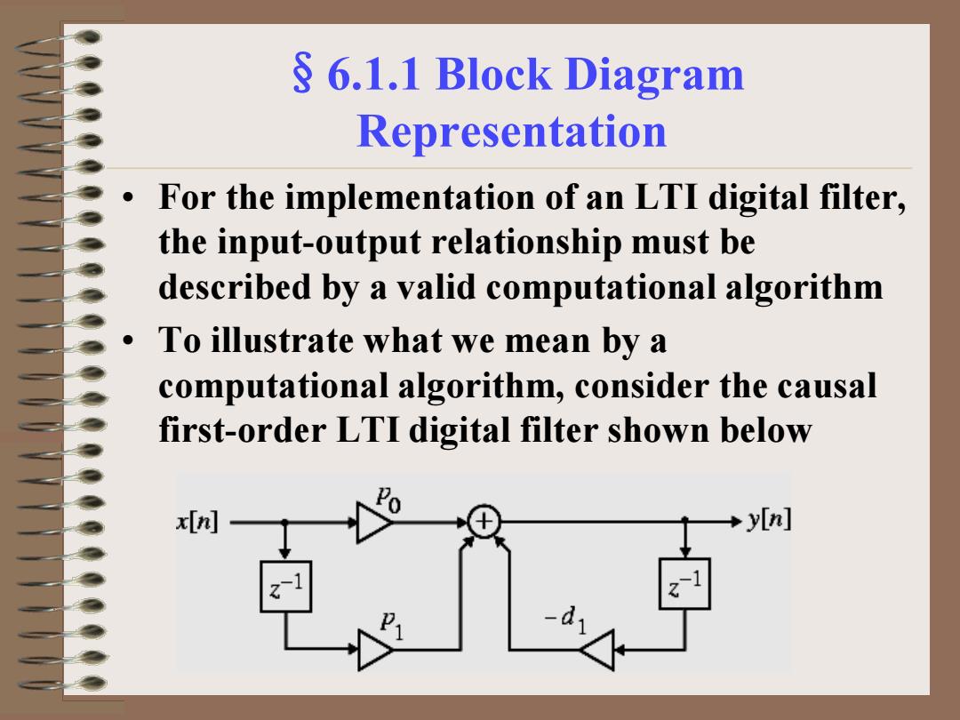
§6.1.1 Block Diagram Representation • For the implementation of an LTI digital filter, the input-output relationship must be described by a valid computational algorithm • To illustrate what we mean by a computational algorithm, consider the causal first-order LTI digital filter shown below
§6.1.1 Block Diagram Representation Each step of the calculation requires a knowledge of the previously calculated value of the output sample (delayed value of the output),the present value of the input sample, and the previous value of the input sample (delayed value of the input) As a result,the first-order difference equation can be interpreted as a valid computational algorithm
§6.1.1 Block Diagram Representation • Each step of the calculation requires a knowledge of the previously calculated value of the output sample (delayed value of the output), the present value of the input sample, and the previous value of the input sample (delayed value of the input) • As a result, the first-order difference equation can be interpreted as a valid computational algorithm

S 6.1.2 Basic Building Blocks The computational algorithm of an LTI digital filter can be conveniently represented in block diagram form using the basic building blocks shown below x[n] wn] Multiplier Adder x(n] xInl yn] Unit delay Pick-off node
§6.1.2 Basic Building Blocks • The computational algorithm of an LTI digital filter can be conveniently represented in block diagram form using the basic building blocks shown below x[n] y[n] w[n] + A x[n] y[n] y[n] −1 x[n] z x[n] x[n] x[n] Adder Unit delay Multiplier Pick-off node
6.1.3 Analysis of Block Diagrams Carried out by writing down the expressions for the output signals of each adder as a sum of its input signals,and developing a set of equations relating the filter input and output signals in terms of all internal signals Eliminating the unwanted internal variables then results in the expression for the output signal as a function of the input signal and the filter parameters that are the multiplier coefficients
§6.1.3 Analysis of Block Diagrams • Carried out by writing down the expressions for the output signals of each adder as a sum of its input signals, and developing a set of equations relating the filter input and output signals in terms of all internal signals • Eliminating the unwanted internal variables then results in the expression for the output signal as a function of the input signal and the filter parameters that are the multiplier coefficients

6.2 Equivalent Structures Two digital filter structures are defined to be equivalent if they have the same transfer function We describe next a number of methods for the generation of equivalent structures However,a fairly simple way to generate an equivalent structure from a given realization is via the transpose operation
§6.2 Equivalent Structures • Two digital filter structures are defined to be equivalent if they have the same transfer function • We describe next a number of methods for the generation of equivalent structures • However, a fairly simple way to generate an equivalent structure from a given realization is via the transpose operation