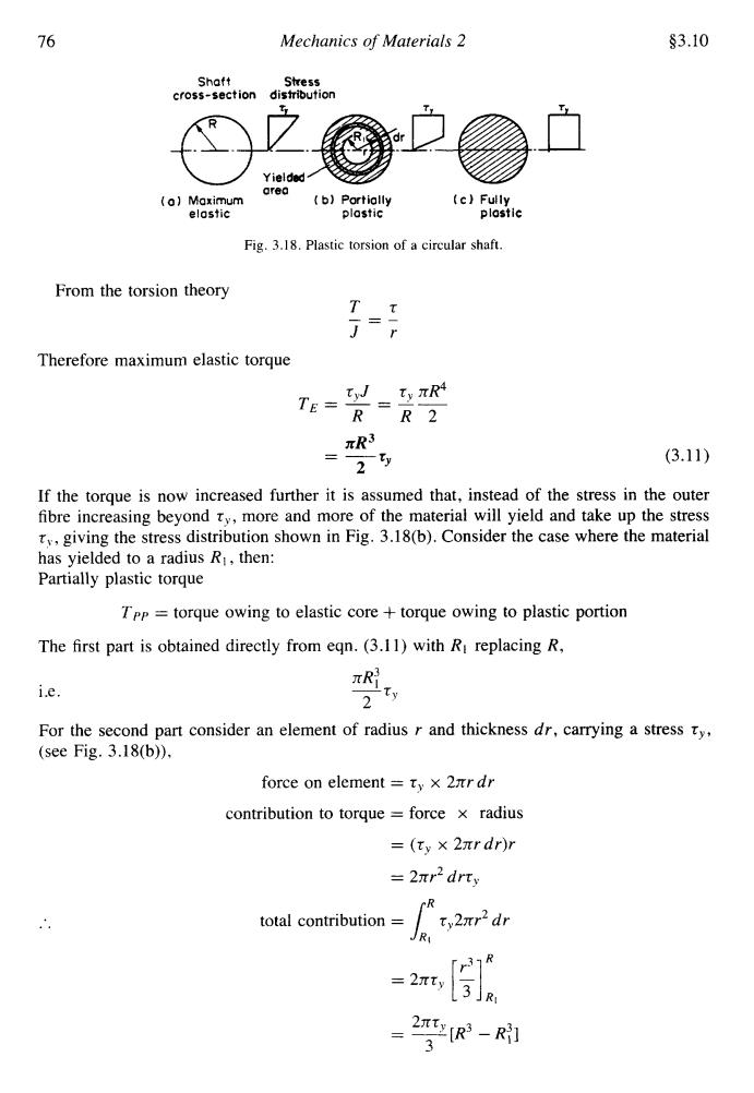
76 Mechanics of Materials 2 §3.10 Shaft Stress cross-section distribution Yielded 0r60 (a】Maximum (b】Partially (c)Fully elostic plostic plostic Fig.3.18.Plastic torsion of a circular shaft. From the torsion theory T T = Therefore maximum elastic torque TE= tW_t,πR4 RR2 R3 25 (3.11) If the torque is now increased further it is assumed that,instead of the stress in the outer fibre increasing beyond ty,more and more of the material will yield and take up the stress ty,giving the stress distribution shown in Fig.3.18(b).Consider the case where the material has yielded to a radius Ri,then: Partially plastic torque TPp torque owing to elastic core +torque owing to plastic portion The first part is obtained directly from eqn.(3.11)with Ri replacing R, i.e. 2 For the second part consider an element of radius r and thickness dr,carrying a stress ty, (see Fig.3.18(b)). force on element ty x 2r dr contribution to torque force x radius =(ty×2πrdr)r =2πr2drty R total contribution ty2nr2dr 2T (R3-Rl 3
76 Mechanics of Materials 2 $3.10 Shaft Stress cross-section disbibution Y isldrd ore0 (01 Maximum (b) Portiolly (c) Fully elostic plostic plostlc Fig. 3.18. Plastic torsion of a circular shaft. From the torsion theory Tt Therefore maximum elastic torque t,J t, nR4 R R2 nR3 TE = - = -- -- (3.1 1) If the torque is now increased further it is assumed that, instead of the stress in the outer fibre increasing beyond T,, more and more of the material will yield and take up the stress t, , giving the stress distribution shown in Fig. 3.18(b). Consider the case where the material has yielded to a radius R1, then: Partially plastic torque 2 ty - Tpp = torque owing to elastic core + torque owing to plastic portion The first part is obtained directly from eqn. (3.1 1) with RI replacing R, XR; i.e. 2 SY For the second part consider an element of radius r and thickness dr, canying a stress ry, (see Fig. 3.18(b)), force on element = T, x 2nrdr contribution to torque = force x radius = (tv x 2nrdr)r = 2nr2 drt, total contribution = IR: t,2nr2 dr

§3.11 Strains Beyond the Elastic Limit 77 Therefore,partially plastic torque 2,+3R3-R 2[4R3-R] (3.12) 6 In Fig.3.18(c)the torque has now been increased until the whole cross-section has yielded, i.e.become plastic.The torque required to reach this situation is then easily determined from eqn.(3.12)since R =0. fully plastic torque T π×4R3 6 ty 3 (3.13) There is thus a considerable torque capacity beyond that required to produce initial yield, the ratio of fully plastic to maximum elastic torques being TFP2πR3 2 TE3× πR3y 4 二3 The fully plastic torque for a solid shaft is therefore 33%greater than the maximum elastic torque.As in the case of beams this can be taken account of in design procedures to increase the allowable torque which can be carried by the shaft or it may be treated as an additional safety factor.In any event it must be remembered that should stresses in the shaft at any time exceed the yield point for the material,then some permanent deformation will occur. 3.11.Angles of twist of shafts strained beyond the elastic limit Angles of twist of shafts in the partially plastic condition are calculated on the basis of the elastic core only,thus assuming that once the outer regions have yielded they no longer offer any resistance to torque.This is in agreement with the basic assumption listed earlier that radial lines remain straight throughout plastic torsion,i.e.Opp =E for the core. For the elastic core,therefore, 后- i.e. Opp= L (3.14) RG 3.12.Plastic torsion of hollow tubes Consider the hollow tube of Fig.3.19 with internal radius Ri and external radius R subjected to a torque sufficient to produce yielding to a radius R2.The torque carried by the
$3.11 Strains Beyond the Elastic Limit 77 Therefore, partially plastic torque nR? 2rs TPP = -5, + -r [R - R,] 2 3v (3.12) In Fig. 3.lS(c) the torque has now been increased until the whole cross-section has yielded, i.e. become plastic. The torque required to reach this situation is then easily determined from eqn. (3.12) since R, = 0. rsr', 3 fully plastic torque TFP = A x 4R- 6 .. 2r 3 = -R zy 3 (3.13) There is thus a considerable torque capacity beyond that required to produce initial yield, the ratio of fully plastic to maximum elastic torques being 4 3 -- The fully plastic torque for a solid shaft is therefore 33% greater than the maximum elastic torque. As in the case of beams this can be taken account of in design procedures to increase the allowable torque which can be carried by the shaft or it may be treated as an additional safety factor. In any event it must be remembered that should stresses in the shaft at any time exceed the yield point for the material, then some permanent deformation will occur. 3.11. Angles of twist of shafts strained beyond the elastic limit Angles of twist of shafts in the partially plastic condition are calculated on the basis of the elastic core only, thus assuming that once the outer regions have yielded they no longer offer any resistance to torque. This is in agreement with the basic assumption listed earlier that radial lines remain straight throughout plastic torsion, i.e. Opp = 0, for the core. For the elastic core, therefore, i.e. r,L epp = A RIG 3.12. Plastic torsion of hollow tubes (3.14) Consider the hollow tube of Fig. 3.19 with internal radius R, and external radius R subjected to a torque sufficient to produce yielding to a radius R2. The torque carried by the
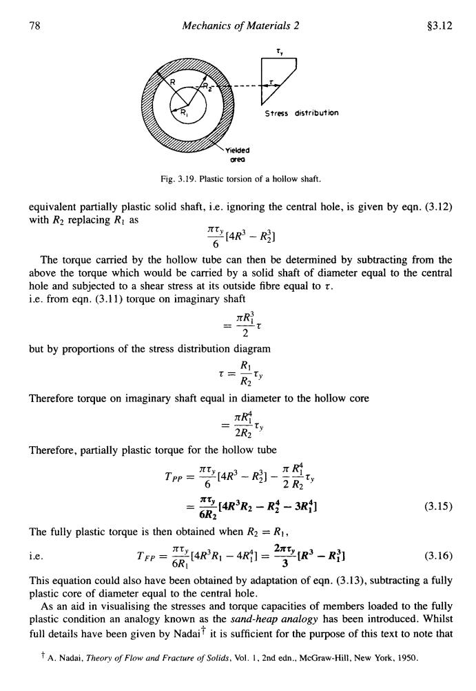
78 Mechanics of Materials 2 $3.12 Stress distribution Yielded orea Fig.3.19.Plastic torsion of a hollow shaft. equivalent partially plastic solid shaft,i.e.ignoring the central hole,is given by eqn.(3.12) with R2 replacing Rt as [4R3-R] 6 The torque carried by the hollow tube can then be determined by subtracting from the above the torque which would be carried by a solid shaft of diameter equal to the central hole and subjected to a shear stress at its outside fibre equal to r. i.e.from eqn.(3.11)torque on imaginary shaft 2 but by proportions of the stress distribution diagram R t彡R Iw Therefore torque on imaginary shaft equal in diameter to the hollow core y 2R2 Therefore,partially plastic torque for the hollow tube T加-管ae--, [4R3R2-R经-3R打 (3.15) 6R2 The fully plastic torque is then obtained when R2=R1, i.e. 1p=流4RR-41-2空- (3.16) This equation could also have been obtained by adaptation of eqn.(3.13),subtracting a fully plastic core of diameter equal to the central hole. As an aid in visualising the stresses and torque capacities of members loaded to the fully plastic condition an analogy known as the sand-heap analogy has been introduced.Whilst full details have been given by Nadaif it is sufficient for the purpose of this text to note that TA.Nadai,Theory of Flow and Fracture of Solids,Vol.1,2nd edn..McGraw-Hill,New York,1950
78 Mechanics of Materials 2 $3.12 Stress distribution aea Fig. 3.19. Plastic torsion of a hollow shaft. equivalent partially plastic solid shaft, i.e. ignoring the central hole, is given by eqn. (3.12) with R2 replacing R1 as 7[4R3 - R;] The torque carried by the hollow tube can then be determined by subtracting from the above the torque which would be carried by a solid shaft of diameter equal to the central hole and subjected to a shear stress at its outside fibre equal to t. i.e. from eqn. (3.1 1) torque on imaginary shaft but by proportions of the stress distribution diagram Therefore torque on imaginary shaft equal in diameter to the hollow core ITRf -- 2R2 " Therefore, partially plastic torque for the hollow tube XtY 3 3 XR;' Tpp = -[4R - R2] - --ty 6 2 R2 = 2[4R3R2 - Ri - 3R;] xr 6R2 The fully plastic torque is then obtained when R2 = R1, i.e. (3.15) (3.16) This equation could also have been obtained by adaptation of eqn. (3.13), subtracting a fully plastic core of diameter equal to the central hole. As an aid in visualising the stresses and torque capacities of members loaded to the fully plastic condition an analogy known as the sand-heap analogy has been introduced. Whilst full details have been given by Nadait it is sufficient for the purpose of this text to note that A. Nadai, Theory ofFlow and Fracture of Solids, Vol. I, 2nd edn., McGraw-Hill, New York, 1950
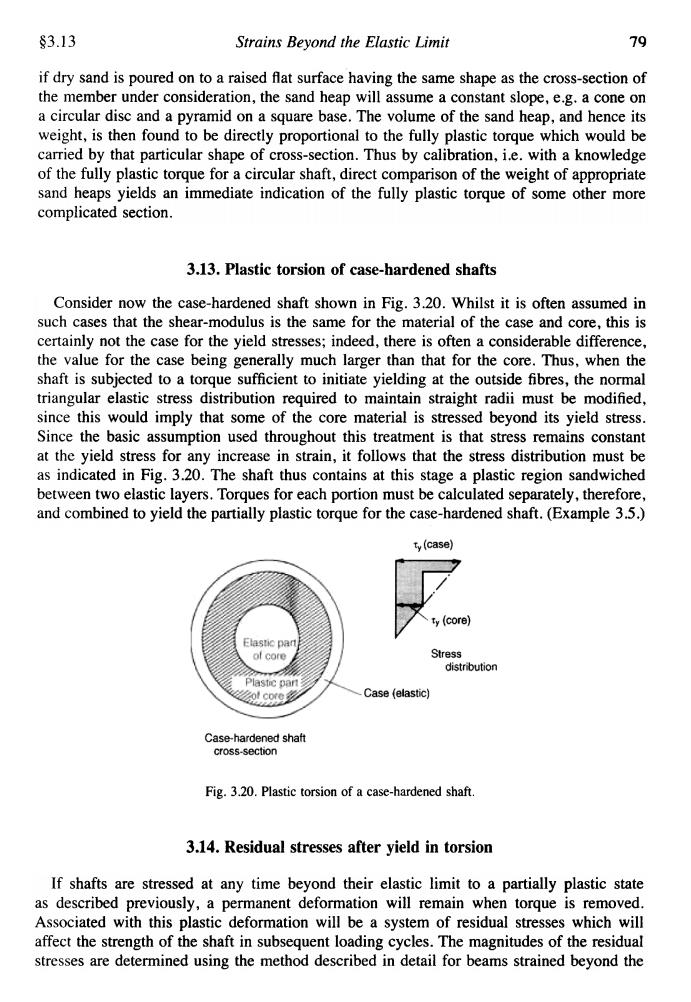
83.13 Strains Beyond the Elastic Limit 79 if dry sand is poured on to a raised flat surface having the same shape as the cross-section of the member under consideration,the sand heap will assume a constant slope,e.g.a cone on a circular disc and a pyramid on a square base.The volume of the sand heap,and hence its weight,is then found to be directly proportional to the fully plastic torque which would be carried by that particular shape of cross-section.Thus by calibration,i.e.with a knowledge of the fully plastic torque for a circular shaft,direct comparison of the weight of appropriate sand heaps yields an immediate indication of the fully plastic torque of some other more complicated section. 3.13.Plastic torsion of case-hardened shafts Consider now the case-hardened shaft shown in Fig.3.20.Whilst it is often assumed in such cases that the shear-modulus is the same for the material of the case and core,this is certainly not the case for the yield stresses;indeed,there is often a considerable difference, the value for the case being generally much larger than that for the core.Thus,when the shaft is subjected to a torque sufficient to initiate yielding at the outside fibres,the normal triangular elastic stress distribution required to maintain straight radii must be modified, since this would imply that some of the core material is stressed beyond its yield stress. Since the basic assumption used throughout this treatment is that stress remains constant at the yield stress for any increase in strain,it follows that the stress distribution must be as indicated in Fig.3.20.The shaft thus contains at this stage a plastic region sandwiched between two elastic layers.Torques for each portion must be calculated separately,therefore, and combined to yield the partially plastic torque for the case-hardened shaft.(Example 3.5.) t(case) ty (core) Elastic part of core Stress distribution Plastic part Case (elastic) Case-hardened shaft cross-section Fig.3.20.Plastic torsion of a case-hardened shaft. 3.14.Residual stresses after yield in torsion If shafts are stressed at any time beyond their elastic limit to a partially plastic state as described previously,a permanent deformation will remain when torque is removed. Associated with this plastic deformation will be a system of residual stresses which will affect the strength of the shaft in subsequent loading cycles.The magnitudes of the residual stresses are determined using the method described in detail for beams strained beyond the
§3.13 Strains Beyond the Elastic Limit 7q if dry sand is poured on to a raised flat surface having the same shape as the cross-section of the member under consideration, the sand heap will assume a constant slope, e.g. a cone on a circular disc and a pyramid on a square base. The volume of the sand heap, and hence its weight, is then found to be directly proportional to the fully plastic torque which would be carried by that particular shape of cross-section. Thus by calibration, i.e. with a knowledge of the fully plastic torque for a circular shaft, direct comparison of the weight of appropriate sand heaps yields an immediate indication of the fully plastic torque of some other more complicated section. 3.13. Plastic torsion of case-hardened shafts Consider now the case-hardened shaft shown in Fig. 3.20. Whilst it is often assumed in such cases that the shear-modulus is the same for the material of the case and core, this is certainly not the case for the yield stresses; indeed, there is often a considerable difference, the value for the case being generally much larger than that for the core. Thus, when the shaft is subjected to a torque sufficient to initiate yielding at the outside fibres, the normal triangular elastic stress distribution required to maintain straight radii must be modified, since this would imply that some of the core material is stressed beyond its yield stress. Since the basic assumption used throughout this treatment is that stress remains constant at the yield stress for any increase in strain, it follows that the stress distribution must be as indicated in Fig. 3.20. The shaft thus contains at this stage a plastic region sandwiched between two elastic layers. Torques for each portion must be calculated separately, therefore, and combined to yield the partially plastic torque for the case-hardened shaft. (Example 3.5.) Fig. 3.20. Plastic torsion of a case-hardened shaft 3.14. Residual stresses after yield in torsion If shafts are stressed at any time beyond their elastic limit to a partially plastic state as described previously, a permanent deformation will remain when torque is removed. Associated with this plastic deformation will be a system of residual stresses which will affect the strength of the shaft in subsequent loading cycles. The magnitudes of the residual stresses are determined using the method described in detail for beams strained beyond the