§3.8 Strains Beyond the Elastic Limit 71 and x=L/3 when d=D (i.e.section elastic) The yielded portion of the beam is thus as indicated in Fig.3.10. Yielded area Fig.3.10.Yielded area in beam carrying central point load. Other beam support and loading cases may be treated similarly.That for a simply supported beam carrying a uniformly distributed load produces linear boundaries to the yielded areas as shown in Fig.3.11. Uniformly distributed load xxxxseeseeeeeeeeaeeeee Yielded orea Fig.3.11.Yielded area in beam carrying uniformly distributed load. 3.8.Collapse loads-plastic limit design Having determined the moment required to produce a plastic hinge for the shape of beam cross-section used in any design it is then necessary to decide from a knowledge of the support and loading conditions how many such hinges are required before complete collapse of the beam or structure takes place,and to calculate the corresponding load.Here it is necessary to consider a plastic hinge as a pin-joint and to decide how many pin-joints are required to convert the structure into a "mechanism".If there are a number of points of "local"maximum B.M.,i.e.peaks in the B.M.diagram,the first plastic hinge will form at the numerical maximum;if further plastic hinges are required these will occur successively at the next highest value of maximum B.M.etc.It is assumed that when a plastic hinge has developed at any cross-section the moment of resistance at that point remains constant until collapse of the whole structure takes place owing to the formation of the required number of further plastic hinges. Consider,therefore,the following loading cases. (a)Simply supported beam or cantilever Whatever the loading system there will only be one point of maximum B.M.and plastic collapse will occur with one plastic hinge at this point (Fig.3.12)
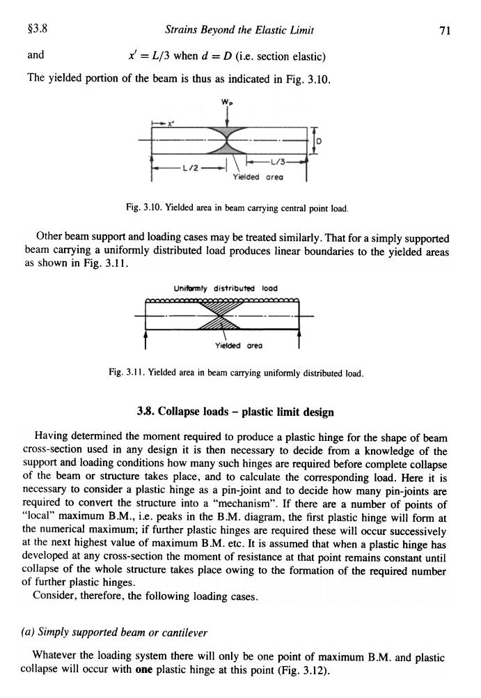
§3.8 Strains Beyond the Elastic Limit 71 and x' = L/3 when d = D (i.e. section elastic) The yielded portion of the beam is thus as indicated in Fig. 3.10. Fig. 3.10. Yielded area in beam carrying central point load Other beam support and loading cases may be treated similarly. That for a simply supported beam carrying a uniformly distributed load produces linear boundaries to the yielded areas as shown in Fig. 3.11. Fig. 3.11. Yielded area in beam carrying uniformly distributed load. 3.8. Collapse loads -plastic limit design Having determined the moment required to produce a plastic hinge for the shape of beam cross-section used in any design it is then necessary to decide from a knowledge of the support and loading conditions how many such hinges are required before complete collapse of the beam or structure takes place, and to calculate the corresponding load. Here it is necessary to consider a plastic hinge as a pin-joint and to decide how many pin-joints are required to convert the structure into a "mechanism". If there are a number of points of "local" maximum B.M., i.e. peaks in the B.M. diagram, the first plastic hinge will form at the numerical maximum; if further plastic hinges are required these will occur successively at the next highest value of maximum B.M. etc. It is assumed that when a plastic hinge has developed at any cross-section the moment of resistance at that point remains constant until collapse of the whole structure takes place owing to the formation of the required number of further plastic hinges. Consider, therefore, the following loading cases. (a) Simply supported beam or cantilever Whatever the loading system there will only be one point of maximum B.M. and plastic collapse will occur with one plastic hinge at this point (Fig. 3.12)
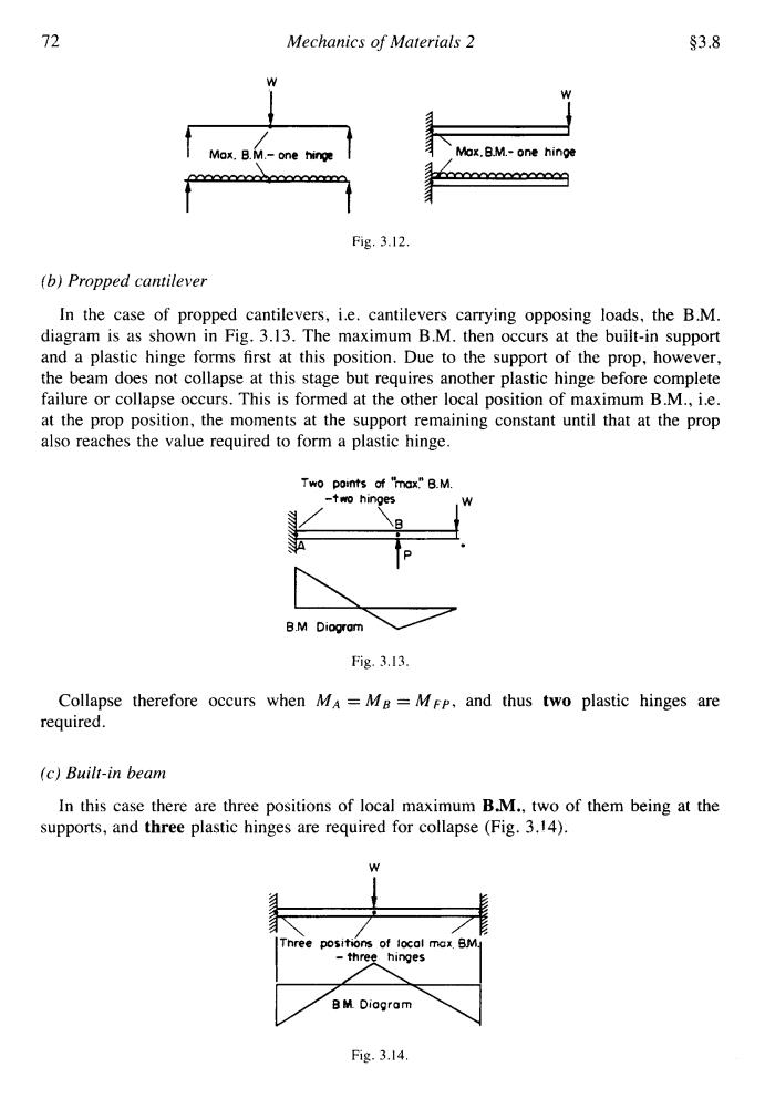
72 Mechanics of Materials 2 $3.8 经 Mox.B.M.-one hinge Max.B.M.-one hinge Fig.3.12. (b)Propped cantilever In the case of propped cantilevers,i.e.cantilevers carrying opposing loads,the B.M. diagram is as shown in Fig.3.13.The maximum B.M.then occurs at the built-in support and a plastic hinge forms first at this position.Due to the support of the prop,however, the beam does not collapse at this stage but requires another plastic hinge before complete failure or collapse occurs.This is formed at the other local position of maximum B.M.,i.e. at the prop position,the moments at the support remaining constant until that at the prop also reaches the value required to form a plastic hinge. Two points of "max."B.M. -two hinges B.M Diogram Fig.3.13. Collapse therefore occurs when MA =M8 =MFP,and thus two plastic hinges are required. (c)Built-in beam In this case there are three positions of local maximum B.M.,two of them being at the supports,and three plastic hinges are required for collapse (Fig.3.14). Three positions of local max.BM. -three hinges BM Diagram Fig.3.14
72 W i Mechanics of Materials 2 $3.8 rn Mox. B.M.- one hinp Mox.B.M.- one hinge "/ Fig. 3.12 (6) Propped cantilever In the case of propped cantilevers, i.e. cantilevers carrying opposing loads, the B.M. diagram is as shown in Fig. 3.13. The maximum B.M. then occurs at the built-in support and a plastic hinge forms first at this position. Due to the support of the prop, however, the beam does not collapse at this stage but requires another plastic hinge before complete failure or collapse occurs. This is formed at the other local position of maximum B.M., i.e. at the prop position, the moments at the support remaining constant until that at the prop also reaches the value required to form a plastic hinge. Two ooints of "mxl' B.M. B.M L Diagram Fig. 3.13. Collapse therefore occurs when MA = MB = MFP, and thus two plastic hinges are required. (e) Built-in beam In this case there are three positions of local maximum B.M., two of them being at the supports, and three plastic hinges are required for collapse (Fig. 3.14). Three positms of local max BM -three hinges BY Diagram Fig. 3.14
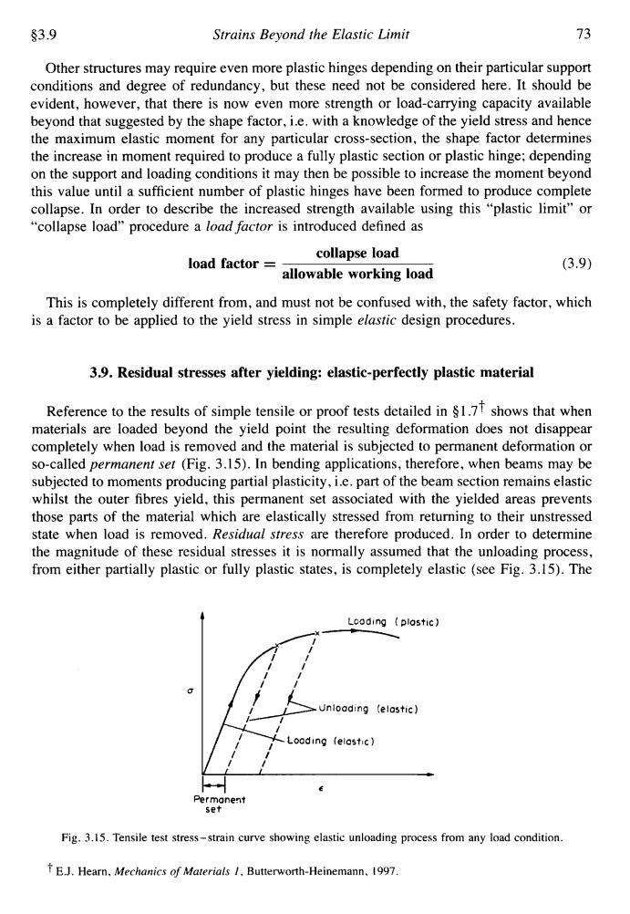
$3.9 Strains Beyond the Elastic Limit 73 Other structures may require even more plastic hinges depending on their particular support conditions and degree of redundancy,but these need not be considered here.It should be evident,however,that there is now even more strength or load-carrying capacity available beyond that suggested by the shape factor,i.e.with a knowledge of the yield stress and hence the maximum elastic moment for any particular cross-section,the shape factor determines the increase in moment required to produce a fully plastic section or plastic hinge:depending on the support and loading conditions it may then be possible to increase the moment beyond this value until a sufficient number of plastic hinges have been formed to produce complete collapse.In order to describe the increased strength available using this "plastic limit"or "collapse load"procedure a load factor is introduced defined as load factor= collapse load (3.9) allowable working load This is completely different from,and must not be confused with,the safety factor,which is a factor to be applied to the yield stress in simple elastic design procedures. 3.9.Residual stresses after yielding:elastic-perfectly plastic material Reference to the results of simple tensile or proof tests detailed in $1.7 shows that when materials are loaded beyond the yield point the resulting deformation does not disappear completely when load is removed and the material is subjected to permanent deformation or so-called permanent set (Fig.3.15).In bending applications,therefore,when beams may be subjected to moments producing partial plasticity,i.e.part of the beam section remains elastic whilst the outer fibres yield,this permanent set associated with the yielded areas prevents those parts of the material which are elastically stressed from returning to their unstressed state when load is removed.Residual stress are therefore produced.In order to determine the magnitude of these residual stresses it is normally assumed that the unloading process, from either partially plastic or fully plastic states,is completely elastic (see Fig.3.15).The Lcoding plastic) Unlooding(elostic)】 -Loading(elastic】 Permanent set Fig.3.15.Tensile test stress-strain curve showing elastic unloading process from any load condition. fE.J.Hearn,Mechanics of Materials 1,Butterworth-Heinemann.1997
53.9 Strains Beyond the Elastic Limit 73 Other structures may require even more plastic hinges depending on their particular support conditions and degree of redundancy, but these need not be considered here. It should be evident, however, that there is now even more strength or load-carrying capacity available beyond that suggested by the shape factor, i.e. with a knowledge of the yield stress and hence the maximum elastic moment for any particular cross-section, the shape factor determines the increase in moment required to produce a fully plastic section or plastic hinge; depending on the support and loading conditions it may then be possible to increase the moment beyond this value until a sufficient number of plastic hinges have been formed to produce complete collapse. In order to describe the increased strength available using this “plastic limit” or “collapse load” procedure a load factor is introduced defined as collapse load allowable working load load factor = (3.9) This is completely different from, and must not be confused with, the safety factor, which is a factor to be applied to the yield stress in simple elastic design procedures. 3.9. Residual stresses after yielding: elastic-perfectly plastic material Reference to the results of simple tensile or proof tests detailed in 8 1 .7t shows that when materials are loaded beyond the yield point the resulting deformation does not disappear completely when load is removed and the material is subjected to permanent deformation or so-called permanent set (Fig. 3.15). In bending applications, therefore, when beams may be subjected to moments producing partial plasticity, i.e. part of the beam section remains elastic whilst the outer fibres yield, this permanent set associated with the yielded areas prevents those parts of the material which are elastically stressed from returning to their unstressed state when load is removed. Residual stress are therefore produced. In order to determine the magnitude of these residual stresses it is normally assumed that the unloading process, from either partially plastic or fully plastic states, is completely elastic (see Fig. 3.15). The 4 U c H c Permanent set Fig. 3.15. Tensile test stress-strain curve showing elastic unloading process from any load condition. t E.J. Hearn, Mechanics of Materials I, Buttenvorth-Heinemann. 1997
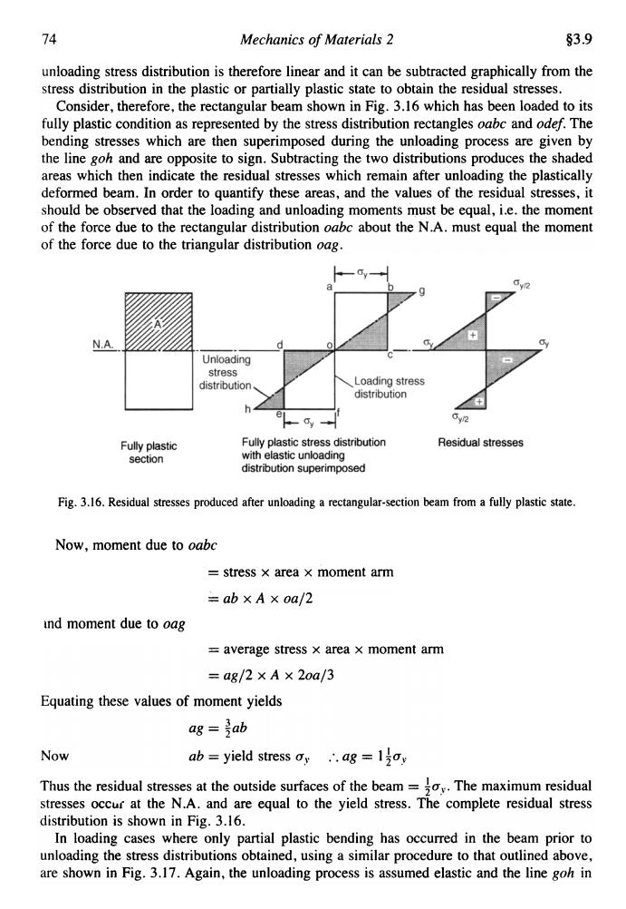
74 Mechanics of Materials 2 3.9 unloading stress distribution is therefore linear and it can be subtracted graphically from the stress distribution in the plastic or partially plastic state to obtain the residual stresses. Consider,therefore,the rectangular beam shown in Fig.3.16 which has been loaded to its fully plastic condition as represented by the stress distribution rectangles oabc and odef.The bending stresses which are then superimposed during the unloading process are given by the line goh and are opposite to sign.Subtracting the two distributions produces the shaded areas which then indicate the residual stresses which remain after unloading the plastically deformed beam.In order to quantify these areas,and the values of the residual stresses,it should be observed that the loading and unloading moments must be equal,i.e.the moment of the force due to the rectangular distribution oabc about the N.A.must equal the moment of the force due to the triangular distribution oag. w2 + N.A Unloading stress distribution Loading stress distribution e 0y2 Fully plastic Fully plastic stress distribution Residual stresses section with elastic unloading distribution superimposed Fig.3.16.Residual stresses produced after unloading a rectangular-section beam from a fully plastic state. Now,moment due to oabc stress x area x moment arm =ab×A×0a/2 and moment due to oag =average stress x area x moment arm =ag/2×A×2oa/3 Equating these values of moment yields ag =jab Now ab=yield stress oy∴,.ag=l2oy Thus the residual stresses at the outside surfaces of the beam=.The maximum residual stresses occur at the N.A.and are equal to the yield stress.The complete residual stress distribution is shown in Fig.3.16. In loading cases where only partial plastic bending has occurred in the beam prior to unloading the stress distributions obtained,using a similar procedure to that outlined above, are shown in Fig.3.17.Again,the unloading process is assumed elastic and the line goh in
74 Mechanics of Materials 2 §3.9 unloading stress distribution is therefore linear and it can be subtracted graphically from the stress distribution in the plastic or partially plastic state to obtain the residual stresses. Consider, therefore, the rectangular beam shown in Fig. 3.16 which has been loaded to its fully plastic condition as represented by the stress distribution rectangles oabc and odef. The bending stresses which are then superimposed during the unloading process are given by the line goh and are opposite to sign. Subtracting the two distributions produces the shaded areas which then indicate the residual stresses which remain after unloading the plastically deformed beam. In order to quantify these areas, and the values of the residual stresses, it should be observed that the loading and unloading moments must be equal, i.e. the moment of the force due to the rectangular distribution oabc about the N .A. must equal the moment of the force due to the triangular distribution oag . Fig. 3.16. Residual stresses produced after unloading a rectangular-section beam from a fully plastic state. Now, moment due to oabc = stress x area x moment arm = ab x A x oa/2 md moment due to oag = average stress x area x moment arm = ag/2 x A x 2oa/3 Equating these values of moment yields ag = ~ab Now ab = yield stress ay ...ag = 14ay Thus the residual stresses at the outside surfaces of the beam = tUy. The maximum residual stresses OCCu( at the N.A. and are equal to the yield stress. The complete residual stress distribution is shown in Fig. 3.16. In loading cases where only partial plastic bending has occurred in the beam prior to unloading the stress distributions obtained, using a similar procedure to that outlined above, are shown in Fig. 3.17. Again, the unloading process is assumed elastic and the line goh in
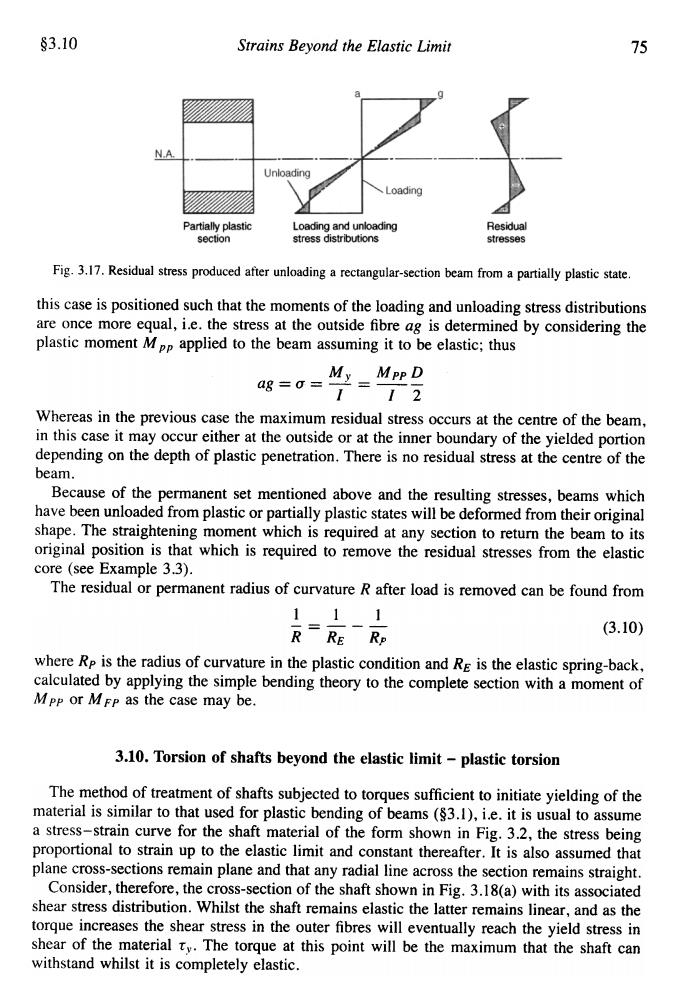
§3.10 Strains Beyond the Elastic Limit 75 Unloading 、Loading Partially plastic Loading and unloading Residual section stress distributions stresses Fig.3.17.Residual stress produced after unloading a rectangular-section beam from a partially plastic state. this case is positioned such that the moments of the loading and unloading stress distributions are once more equal,i.e.the stress at the outside fibre ag is determined by considering the plastic moment Mpp applied to the beam assuming it to be elastic;thus ag=0= My Mpp D 112 Whereas in the previous case the maximum residual stress occurs at the centre of the beam, in this case it may occur either at the outside or at the inner boundary of the yielded portion depending on the depth of plastic penetration.There is no residual stress at the centre of the beam. Because of the permanent set mentioned above and the resulting stresses,beams which have been unloaded from plastic or partially plastic states will be deformed from their original shape.The straightening moment which is required at any section to return the beam to its original position is that which is required to remove the residual stresses from the elastic core (see Example 3.3). The residual or permanent radius of curvature R after load is removed can be found from 111 R=RE一R (3.10) where Rp is the radius of curvature in the plastic condition and Re is the elastic spring-back, calculated by applying the simple bending theory to the complete section with a moment of MPp or MFP as the case may be. 3.10.Torsion of shafts beyond the elastic limit-plastic torsion The method of treatment of shafts subjected to torques sufficient to initiate yielding of the material is similar to that used for plastic bending of beams ($3.1),i.e.it is usual to assume a stress-strain curve for the shaft material of the form shown in Fig.3.2,the stress being proportional to strain up to the elastic limit and constant thereafter.It is also assumed that plane cross-sections remain plane and that any radial line across the section remains straight. Consider,therefore,the cross-section of the shaft shown in Fig.3.18(a)with its associated shear stress distribution.Whilst the shaft remains elastic the latter remains linear,and as the torque increases the shear stress in the outer fibres will eventually reach the yield stress in shear of the material ty.The torque at this point will be the maximum that the shaft can withstand whilst it is completely elastic
§3.10 Strains Beyond the Elastic Limit 75 Fig. 3.17. Residual stress produced after unloading a rectangular-section beam from a partially plastic state. this case is positioned such that the moments of the loading and unloading stress distributions are once more equal, i.e. the stress at the outside fibre ag is determined by considering the plastic moment M pp applied to the beam assuming it to be elastic; thus My Mpp D ag = a = --'- = -- I I 2 Whereas in the previous case the maximum residual stress occurs at the centre of the beam, in this case it may occur either at the outside or at the inner boundary of the yielded portion depending on the depth of plastic penetration. There is no residual stress at the centre of the beam. Because of the permanent set mentioned above and the resulting stresses, beams which have been unloaded from plastic or partially plastic states will be deformed from their original shape. The straightening moment which is required at any section to return the beam to its original position is that which is required to remove the residual stresses from the elastic core (see Example 3.3). The residual or permanent radius of curvature R after load is removed can be found from -= (3.10) R RE where Rp is the radius of curvature in the plastic condition and RE is the elastic spring-back, calculated by applying the simple bending theory to the complete section with a moment of M pp or M FP as the case may be. R., 3.10. Torsion of shafts heyond the elastic limit -plastic torsion The method of treatment of shafts subjected to torques sufficient to initiate yielding of the material is similar to that used for plastic bending of beams (§3.1), i.e. it is usual to assume a stress-strain curve for the shaft material of the form shown in Fig. 3.2, the stress being proportional to strain up to the elastic limit and constant thereafter. It is also assumed that plane cross-sections remain plane and that any radial line across the section remains straight. Consider, therefore, the cross-section of the shaft shown in Fig. 3 .18(a) with its associated shear stress distribution. Whilst the shaft remains elastic the latter remains linear, and as the torque increases the shear stress in the outer fibres will eventually reach the yield stress in shear of the material Ty. The torque at this point will be the maximum that the shaft can withstand whilst it is completely elastic