226 Measurement based statistical channel modeling A integer multiple of At.. Model ses s proposed in Cink (7),valuation of chane the follwn wa 1.Mutual information 2.Channel diversity 3.Demmel condition number of the MIMO channel metrics 4.Environment Characterization Metric (ECM)comparing directly the discrete propagation paths in the channel Clustering methods Four methods can be used for clustering paths: .the hierarchical tree clustering the kPowerMeans clustering .Gaussian-mixture clustering .Estimating clusters directly in the impulse response. custerin this approach can be easily combined using path powers.Unfortunately it turned out that this clusterin method has its when trying to track uster the usering results are quite unstabl dispersive paths.Notice that the raher han clusters here. of many on-sprab paths n ch the dfnon of ceradipeiv Path 8.3.2 Clustering algorithms Definition of MCD Nicolai proposes to use Multipath component distance (MCD)to quantify the difference between two paths.This MCD c scaling metho to scal the differenc complete multipath separation of the radio channel. noenae器artonsnandtctytmsnnteagahrdaaeMobewemwiadinm MCDAOA/AOD.=-2l (8.1) MCD.=.I (8.2) the standard deviation of the delays,and is a scaling factor which can give r suggests to choose MCD VIMCD2+MCD2+MCD (8.3)
226 Measurement based statistical channel modeling • ∆tΛ denotes the cluster lifetime interval. Cluster lifetimes can only be a multiple of this value. The reason for this is that newly born clusters have to fade in and dying clusters need to fade out smoothly. Note that ∆tΛ is an integer multiple of ∆ts. Model evaluation issues As proposed in Czink (2007), evaluation of a channel can be performed in the following ways: 1. Mutual information 2. Channel diversity 3. Demmel condition number of the MIMO channel metrics 4. Environment Characterization Metric (ECM) comparing directly the discrete propagation paths in the channel Clustering methods Four methods can be used for clustering paths: • the hierarchical tree clustering • the KPowerMeans clustering • Gaussian-mixture clustering • Estimating clusters directly in the impulse response. Gaussian mixture (GM) clustering superimposes a specific structure on the clusters. The cluster parameters are assumed to be Gaussian distributed, showing a higher path density in the centre than in its outskirts. For MPC clustering, this approach can be easily combined using path powers. Unfortunately, it turned out that this clustering method has its shortcomings when trying to track clusters since the clustering results are quite unstable. The fourth method is the “potato”-based approach, which is originally proposed for estimating the spreads of a dispersive paths. Notice that the term “dispersive path” is used rather than clusters here. However, a dispersive path can be viewed as consisting of many non-separable paths. In such a sense, the definitions of cluster and a dispersive path are similar. 8.3.2 Clustering algorithms Definition of MCD Nicolai proposes to use Multipath component distance (MCD) to quantify the difference between two paths. This MCD applies specific scaling method to scale the difference between the path parameters in different dimensions. So the parameter differences are combined with the same unit. This MCD is first introduced in Steinbauer et al. (2002) to quantify the complete multipath separation of the radio channel. MCD considers the angular domain and the delay domain. In the angular domain, the MCD between two directions Ω1 and Ω2 is defined as MCDAoA/AoD,ij = 1 2 Ω1 − Ω2 . (8.1) This value has the range of [0, 1]. The MCD of paths in delay domain can be defined as MCDτ,ij = ζτ · |τi − τj | ∆τmax · τstd ∆τmax , (8.2) where ∆τmax = maxi,j{|τi − τj |}, τstd is the standard deviation of the delays, and ζ is a scaling factor which can give more “importance” when necessary. In Czink (2007), the author suggests to choose ζ = 8. Finally the distance between the paths (i, j) is calculated as MCDij = q kMCDΩTx,ijk 2 + kMCDΩRx,ijk 2 + MCD2 τ,ij . (8.3)
Measurement based statistical channel modeling 227 Extension of the MCD in our case a@l油fc gation paths should be also considered when computing the distance between MCDw的=C.-L.a (8.4) △mnx△max C is a scaling factor nce"to the MCD differe aogaihengae&rweCpeettiRrtiodandshowthediereaceoftheresusobainedwihtheproposed Per Cluster Doppler frequency spectrum In the current RCM,the Doppler frequency is added to the MPCs within a cluster in a second step,with the first step equency alu lay,dire ter,w =色 (8.5) In the rCM.the basic version of which is the fundam WINNER I and n ract eristics),and the effects of rotating antenna arrays are neglected The Doppler freg direction of travel of the Tx or Rx.Anyway,these models may not be accurate when both the clusters and Tx or Rx are 1.Using a geometric method and the ray-tracing crith certain physical extension ssible to 3.Derive a model for received signal by cooperating the parametric model of the Doppler frequency spectrum Estimate the parameters from real measurement data MCD without weighting factors usi weca new multipath component distance which relies on the differenc between the bas band received signals with the different path parameters.The ph ors due to the parameters are e o parameter distance in different dimensions Extraction method o racteristics of the clusters are obta ained based on these clusters. In this work,we use MCD-based method to cluster the paths
Measurement based statistical channel modeling 227 Extension of the MCD in our case The Doppler frequencies of the propagation paths should be also considered when computing the distance between two paths. We can use a similar definition for the MCD in Doppler frequency domain with that of the MCD in delay, i.e. MCDν,ij = ζν · |νi − νj | ∆νmax · νstd ∆νmax , (8.4) where ζν is a scaling factor to give different “importance” to the MCD difference. It is quite difficult to understand the meaning of the multiplicative factors for scaling the so-called MCD. But just for comparison purpose, we implement this method and show the difference of the results obtained with the proposed method in the section of “Experimental result”. Per Cluster Doppler frequency spectrum In the current RCM, the Doppler frequency is added to the MPCs within a cluster in a second step, with the first step being the determination of the parameters in delay, directions and attenuations. The Doppler frequency of a cluster, actually only one single Doppler frequency value is provided for the whole cluster, which is calculated by νc = f0 c0 vc, (8.5) In the RCM, the basic version of which is the fundamental modeling method used to generate WINNER I and II models, all paths within a cluster are assigned the same rate of change of their delay (i.e., they show the same Doppler frequency characteristics), and the effects of rotating antenna arrays are neglected. We should be able to show that a good clustering method can give a good match to physical propagation scenario. The Doppler frequency spectrum obtained for a cluster, is somehow related to the movement of the Tx or Rx and direction of travel of the Tx or Rx. Anyway, these models may not be accurate when both the clusters and Tx or Rx are moving. We can do the following steps to obtain the Doppler frequency spectrum for individual clusters. 1. Using a geometric method and the ray-tracing technique, represent the scatterer with certain physical extension by multiple discrete points. Each point results in a propagation path. The Doppler frequency spectrum for such a scatterer can be calculated or derived analytically. 2. Try to parameterize the Doppler frequency spectrum using the characteristics of the scatterer. It is possible to model the scatterer’s physical shape by its center of gravity and the spreads in length and width or depth. 3. Derive a model for received signal by cooperating the parametric model of the Doppler frequency spectrum. 4. Estimate the parameters from real measurement data. MCD without weighting factors One drawback of the MCD defined in Czink (2007) is that the MCD relies on the weighting factors that give different importance to the difference between path parameters. These factors are heuristic and are proposed based on experimental experience. To avoid using heuristic factors, we can define a new multipath component distance which relies on the difference between the baseband received signals with the different path parameters. The phasors due to the parameters are compared. The difference of two phasors due to delay can be easily combined with the difference of two phasors due to Doppler frequency or angles. By doing so, it is not necessary to use heuristic settings to specify the importance of parameter distance in different dimensions. Extraction method We select 3 bursts as one data segment. The estimated paths obtained from these 3 bursts are clustered into a fixed number of clusters. These clusters are considered as the independent realizations of paths in the TR25.996. The statistical characteristics of the clusters are obtained based on these clusters. In this work, we use MCD-based method to cluster the paths

228 Measurement based statistical channel modeling 670 1的0 delay in samples Fig.8.4 Example of the powers of paths versus the delays of the paths.The parameters of the paths are estimated from measurement data collected in a macro suburban environment.The Tx moves at a pedestrian speed,following the first route. used to compute 8.6 whereP=denotes the total power of all the paths,is calculated as 1-p>mn (8.7刀 rewritten a MCD=0.0357.lm-l (8.8) 二然 of the Dopple (8.9) =1 Calculation shows that=-1.1591Hz,=1.9091Hz,and Ar=13.8Hz.Thus,(8.4)turns out to be MCD=0.01C·lw-w,l, (8.10) Nicolai's MCD-ba ironment.The s er-Delay domain the clusters are we aling factors multiplied withand aths. rs for the ct of the path distance MCD and MCD on the overall distance
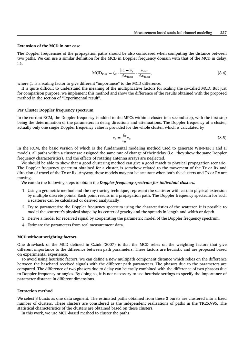
228 Measurement based statistical channel modeling 150 155 160 165 170 175 180 185 0 0.5 1 1.5 2 2.5 3 3.5 x 10⁻⁹ delay in samples Amplitude in linear Fig. 8.4 Example of the powers of paths versus the delays of the paths. The parameters of the paths are estimated from measurement data collected in a macro suburban environment. The Tx moves at a pedestrian speed, following the first route. Fig. 8.4 depicts the power estimates of the paths versus the delays of the paths. In order to implement Nicolai’s clustering method based on the MCD, we calculate the standard deviation στ of the delays. The following equation is used to compute στ : στ = vuut 1 P X L ℓ=1 pℓ · (τℓ − τ¯) 2 (8.6) where P = PN ℓ=1 pℓ denotes the total power of all the paths, τ¯ is calculated as τ¯ = 1 P X L ℓ=1 pℓ · τℓ (8.7) For the example shown in Fig. 8.4, τ¯ is calculated to be 159.6377 delay samples, στ reads 6.4334 delay samples. In addition, ∆τmax is 30 delay samples. Thus, (8.2) can be rewritten as MCDτ,ij = 0.0357 · |τi − τj |. (8.8) It is necessary to explain what the multiplicative factor 0.0357 stands for. We now compute the maximum duration ∆νmax, the mean ν¯ and the standard deviation σν of the Doppler frequencies of the paths. Fig. 8.5 depicts the powers of the paths versus the Doppler frequencies of those paths. The following equations are used to calculate ν¯ and σν ν¯ = 1 P X L ℓ=1 pℓ · νℓ, σν = vuut 1 P X L ℓ=1 pℓ · (νℓ − ν¯) 2 (8.9) Calculation shows that ν¯ = −1.1591Hz, σν = 1.9091Hz, and ∆νmax = 13.8Hz. Thus, (8.4) turns out to be MCDν,ij = 0.01ζν · |νi − νj |, (8.10) Now we show the clustering result when the Nicolai’s clustering method based on MCD is used. The number of clusters is set to 6. The scaling factors ζτ = ζν = 5 are selected. Fig. 8.6 depicts the result obtained when applying Nicolai’s MCD-based clustering method to the estimated 500 paths in a macro suburban environment. The square marks in the plots in Fig. 8.6 indicates the centroid of the clusters. We observe from Fig. 8.6 that the overlapping of the clusters in the angular domain is significant. However, in the Doppler-Delay domain, the clusters are well separated. We have some difficulties to understand this observation. The scaling factors multiplied with |τi − τj | and |νi − νj | are much less than the scaling factor for the directions. But the above observation shows that the distance of paths in the directional domain does not change significantly for all the paths. Although the scaling factors for the delay and Doppler frequency are small, the impact of the path distance MCDτ,ij and MCDν,ij on the overall distance MCDij is more significant than the impact of MCDΩAoA,ij

Measurement based statistical channel modeling 229 670 -8 Doppler frequency in H of paths v meters of the paths are estimated 10 dB No.of clusters 6 8.3.3 Experimental results for path clustering C时酸尚。 o Czink(2007).We would like to verify ne scena macroce to one cluster.We can observe that,the clusters are more well-sep rated in the delay and Dopple frequency do domanbeiogoaiferendstersasepeced,PathshiedinhecenierofheEoAAoAigueaepltnodstes nich arelso delay domains.This clus ing res .This is due to the limited number of custers selected in Fig.8.7 depicts the convergence rate of the lu ers spreh ds in d Doppler ters sprea stabilize.This indicates that the KPower-mean approach does exhibit an excellent convergence property
Measurement based statistical channel modeling 229 −10 −8 −6 −4 −2 0 2 4 6 0 0.5 1 1.5 2 2.5 3 3.5 x 10⁻⁹ Doppler frequency in Hz Amplitude in linear Fig. 8.5 Example of the powers of paths versus the Doppler frequencies of the paths. The parameters of the paths are estimated from measurement data collected in a macro suburban environment. The Tx moves at a pedestrian speed, following the first route. Table 8.1 Parameter setting in the SAGE algorithm and in the clustering algorithm. No. of paths 20 No. of iterations 5 Dynamic range 10 dB No. of bursts in one segment 3 No. of clusters 6 8.3.3 Experimental results for path clustering We have determined that one data segment is composed of 3 consecutive bursts. The SAGE algorithm was used to process the Oulu channel measurement data. The path estimates were grouped using the MCD-based approach as described in Czink (2007). Notice that the parameter ζ is heuristically pre-defined to be 5 according to Czink (2007). We would like to verify how the clustering algorithm performs when ζ takes different values. In the following, we select the data collected in the scenario “macrocell, suburban, Pedestrian route 1” and choose ζτ = ζν = 5 and 8 for path clustering respectively. Here, ζτ and ζν denote the weighting factor, i.e. a multiplicative factor, for the distance in delay and in Doppler frequency respectively. Table 8.1 depicts the setting used in the SAGE algorithm for processing the data. Fig. 8.6 depicts the constellation of paths and the clustering results when ζτ = ζν = 1, 5, 8, 20 is selected respectively. The paths with same color belong to one cluster. We can observe that when ζ increases, the clusters are more well-separated in the delay and Doppler frequency domains. From these results, we see that ζτ = ζν = 5 to 8 is more reasonable. From Fig. 8.6 it can be observed that for ζτ = ζν = 5 or 8, the paths which can be well separated in the EoA-AoA domain belong to different clusters as expected. Paths mixed in the center of the EoA-AoA figure are split into clusters which are well separated in the Doppler frequency and delay domains. This clustering result looks quite promising. We can also observe some outliers in the EoA-AoA domain that are assigned to clusters whose centroid are far from the outliers’ locations. This is due to the limited number of clusters selected in the algorithm. Fig. 8.7 depicts the convergence rate of the clusters’ spreads in delay, Doppler frequency, azimuth and elevation of arrival, versus the iteration number. It can be observed that after 5 iterations, the values of the clusters’ spreads stabilize. This indicates that the KPower-mean approach does exhibit an excellent convergence property

230 Measurement based statistical channel modeling 第白' 1o2c0nmpk 20 -10 20 -60 20 10 。 -60 200 20
230 Measurement based statistical channel modeling 150 160 170 180 190 200 −50 −40 −30 −20 −10 0 10 20 Delay in samples Doppler frequency in Hz −100 −50 0 50 100 −80 −60 −40 −20 0 20 40 60 Azimuth of Arrival [ ◦ ] Elevation of Arrival [ ◦ ] 150 160 170 180 190 200 −50 −40 −30 −20 −10 0 10 20 Delay in samples Doppler frequency in Hz −100 −50 0 50 100 −80 −60 −40 −20 0 20 40 60 Azimuth of Arrival [ ◦ ] Elevation of Arrival [ ◦ ] 150 160 170 180 190 200 −50 −40 −30 −20 −10 0 10 20 Delay in samples Doppler frequency in Hz −100 −50 0 50 100 −80 −60 −40 −20 0 20 40 60 Azimuth of Arrival [ ◦ ] Elevation of Arrival [ ◦ ] 150 160 170 180 190 200 −50 −40 −30 −20 −10 0 10 20 Delay in samples Doppler frequency in Hz −100 −50 0 50 100 −80 −60 −40 −20 0 20 40 60 Azimuth of Arrival [ ◦ ] Elevation of Arrival [ ◦ ] Fig. 8.6 Constellation of the paths in the 6 clusters in Doppler frequency and delay domains (to the left), and in DoA (to the right), with ζτ = ζν = 1 (first row), ζτ = ζν = 5 (second row), ζτ = ζν = 8 (third row) and ζτ = ζν = 20 (bottom row)