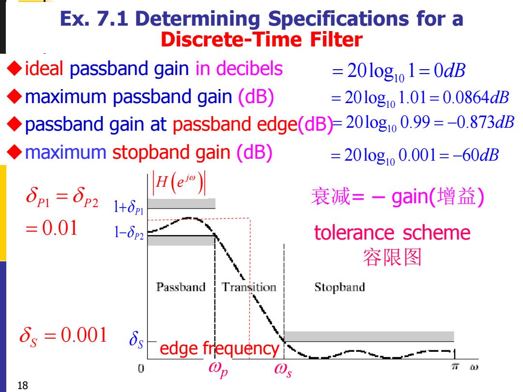
Ex.7.1 Determining Specifications for a Discrete-Time Filter ideal passband gain in decibels =20l0gio1=0dB maximum passband gain(dB) =201ogo1.01=0.0864dB passband gain at passband edge(dB)=20l0g10 0.99=-0.873dB maximum stopband gain(dB) =201og1o0.001=-60dB δp1=δp2 H(e 1+δp1 衰减=一gain(增益) =0.01 1-6p2 tolerance scheme 容限图 Passband Transition Stopband δs=0.001 edge frequency 18
( ) j H e 18 Ex. 7.1 Determining Specifications for a Discrete-Time Filter ◆ideal passband gain in decibels ◆maximum passband gain (dB) ◆passband gain at passband edge(dB) ◆maximum stopband gain (dB) 1 2 0.01 P P = = 0.001 S = tolerance scheme 容限图 1+ P1 1− P2 S 10 = = 20log 1 0dB 10 = = 20log 1.01 0.0864dB 10 = = − 20log 0.99 0.873dB 10 = = − 20log 0.001 60dB edge frequency 衰减= − gain(增益) p s
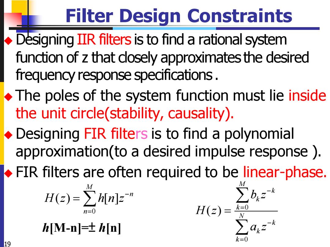
Filter Design Constraints Designing IIR filters is to find a rational system function of z that dosely approximates the desired frequency response specifications .The poles of the system function must lie inside the unit circle(stability,causality). Designing FIR filters is to find a polynomial approximation(to a desired impulse response ) FIR filters are often required to be linear-phase. H(z)=∑hn]z” ∑bzt n=0 H(z)= k= hM-n=±h[n ∑a4z k=0 19
19 Filter Design Constraints ◆ Designing IIR filters is to find a rational system function of z that closely approximates the desired frequency response specifications . ◆ The poles of the system function must lie inside the unit circle(stability, causality). ◆ Designing FIR filters is to find a polynomial approximation(to a desired impulse response ). ◆ FIR filters are often required to be linear-phase. 0 0 ( ) M k k k N k k k b z H z a z − = − = = 0 ( ) [ ] M n n H z h n z− = = h[M-n]=±h[n]

Filter Design Techniques 7.2 Design of Discrete-Time IIR Filters From Continuous-Time Filters 20
20 Filter Design Techniques 7.2 Design of Discrete-Time IIR Filters From Continuous-Time Filters
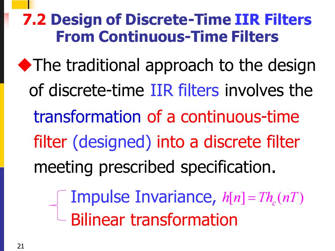
7.2 Design of Discrete-Time IIR Filters From Continuous-Time Filters The traditional approach to the design of discrete-time IIR filters involves the transformation of a continuous-time filter (designed)into a discrete filter meeting prescribed specification. Impulse Invariance,h[n]=Th (nT) Bilinear transformation 21
21 7.2 Design of Discrete-Time IIR Filters From Continuous-Time Filters ◆The traditional approach to the design of discrete-time IIR filters involves the transformation of a continuous-time filter (designed) into a discrete filter meeting prescribed specification. Impulse Invariance, Bilinear transformation[ ] ( ) c h n Th nT =
Three Reasons for designing DT filter by. transformation of CT filter (designed) 1.The art of continuous-time IIR filter design is highly advanced,and useful results can be achieved, it is advantageous to use the design procedures already developed for continuous-time filters. 22
22 Three Reasons for designing DT filter by transformation of CT filter (designed) 1. The art of continuous-time IIR filter design is highly advanced, and useful results can be achieved, it is advantageous to use the design procedures already developed for continuous-time filters