S 7.4 IIR Digital Filter Design: Bilinear Transformation Method Steps in the design of a digital filter- (1)Prewarp (p)to find their analog equivalents (p) (2)Design the analog filter Ha(s) (3)Design the digital filter G(z)by applying bilinear transformation to Ha(s) Transformation can be used only to design digital filters with prescribed magnitude response with piecewise constant values Transformation does not preserve phase response of analog filter
§7.4 IIR Digital Filter Design: Bilinear Transformation Method • Steps in the design of a digital filter - (1) Prewarp (ωp, ωs) to find their analog equivalents (Ωp, Ωs) (2) Design the analog filter Ha(s) (3) Design the digital filter G(z) by applying bilinear transformation to Ha(s) • Transformation can be used only to design digital filters with prescribed magnitude response with piecewise constant values • Transformation does not preserve phase response of analog filter
S 7.4 IIR Digital Filter Design: Bilinear Transformation Method Example-Consider Ha(s)= De s+2。 Applying bilinear transformation to the above we get the transfer function of a first-order digital lowpass Butterworth filter 2.(1+z1) Ge)=H.),0-2)+2.0+')
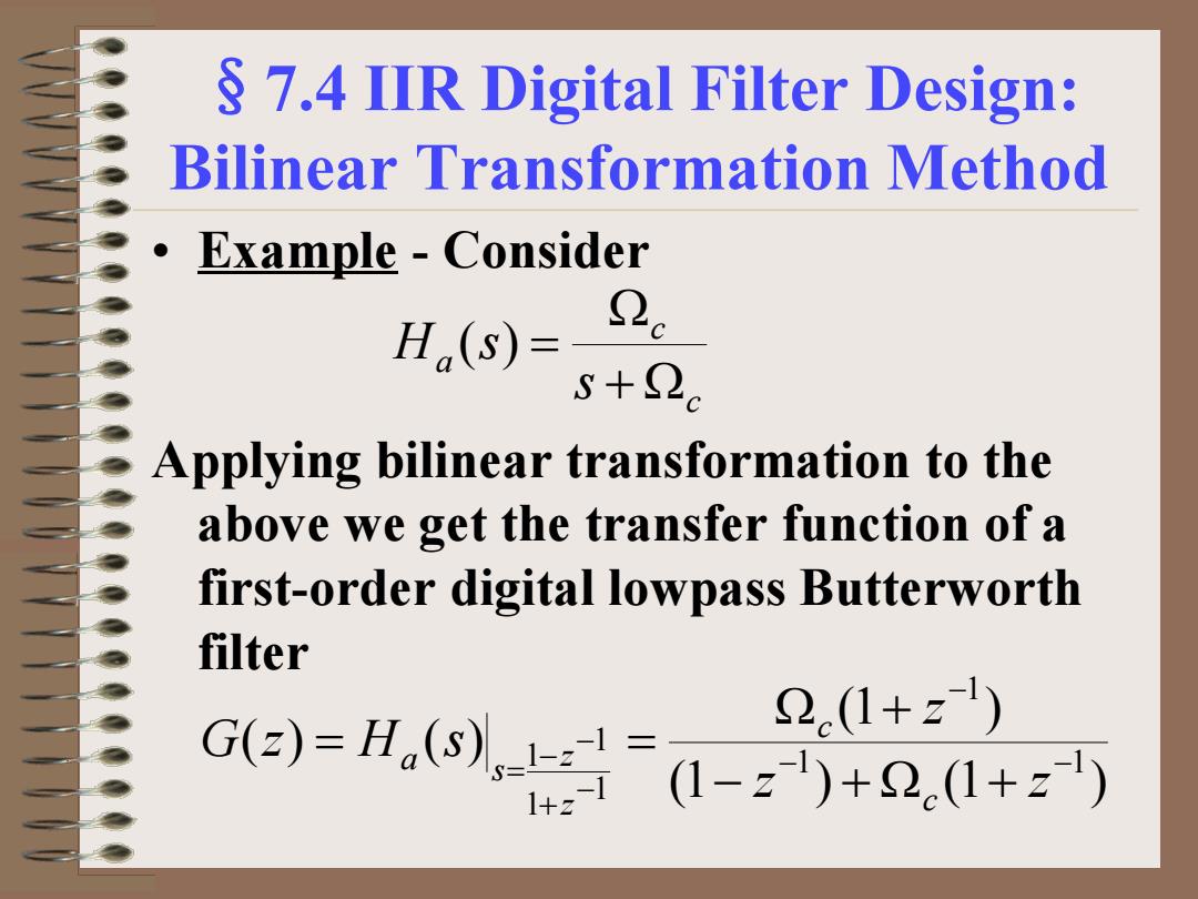
§7.4 IIR Digital Filter Design: Bilinear Transformation Method Applying bilinear transformation to the above we get the transfer function of a first-order digital lowpass Butterworth filter c c a s H s + Ω Ω ( ) = (1 ) (1 ) (1 ) ( ) ( ) 1 1 1 1 1 1 1 − − − − + − − = − + Ω + Ω + = = z z z G z H s c c z z s a • Example - Consider
S 7.4 IIR Digital Filter Design: Bilinear Transformation Method Rearranging terms we get G() 1-c.1+z1 2 1-az1 where 1-2c_1-tan(oc/2) 0= 1+2c1+tan(oc/2)
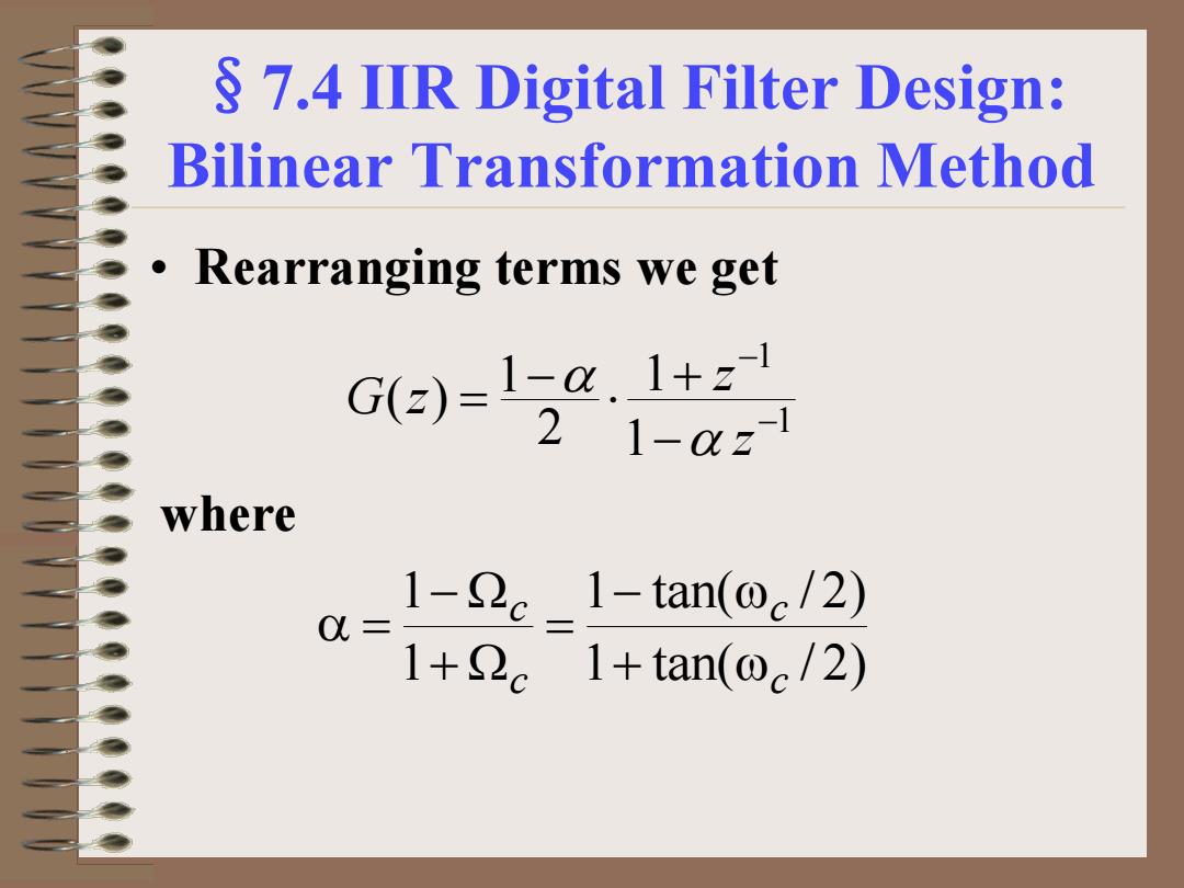
§7.4 IIR Digital Filter Design: Bilinear Transformation Method • Rearranging terms we get 1 1 1 1 2 1 ( ) − − − + ⋅ − = z z G z α α 1 tan( / 2) 1 tan( / 2) 1 1 c c c c + ω − ω = + Ω − Ω α = where

S 7.4 IIR Digital Filter Design: Bilinear Transformation Method Example-Consider the second-order analog notch transfer function s2+2 Ha(s)=s2+Bs+So for which Ha(j2o)川=0 HaG0)川=H(jo)川=0 o is called the notch frequency If H(j2)=H(j )=1/2 then B=22-2 is the 3-dB notch bandwidth
§7.4 IIR Digital Filter Design: Bilinear Transformation Method for which |Ha(jΩ0)| = 0 |Ha(j0)| = |Ha(j∞)| = 0 • Ω0 is called the notch frequency • If |Ha(jΩ2)| = |Ha(jΩ1)| =1/√2 then B = Ω2 - Ω1 is the 3-dB notch bandwidth 2 2 2 2 ( ) o o a s Bs s H s + + Ω + Ω = • Example - Consider the second-order analog notch transfer function
S 7.4 IIR Digital Filter Design: Bilinear Transformation Method .Then G(2)=Ha(S) + 1+22)-21-2)z1+(1+23)z2 (1+22+B)-2(1-22)z1+(1+22-B)z2 1+ 1-2Bz1+z2 21-2B(1+)z1+auz2 where 1+22-B1-tan(Bn/2) 0= 1+2+B1+tan(B,w/2) B -22 1+2 cos@o
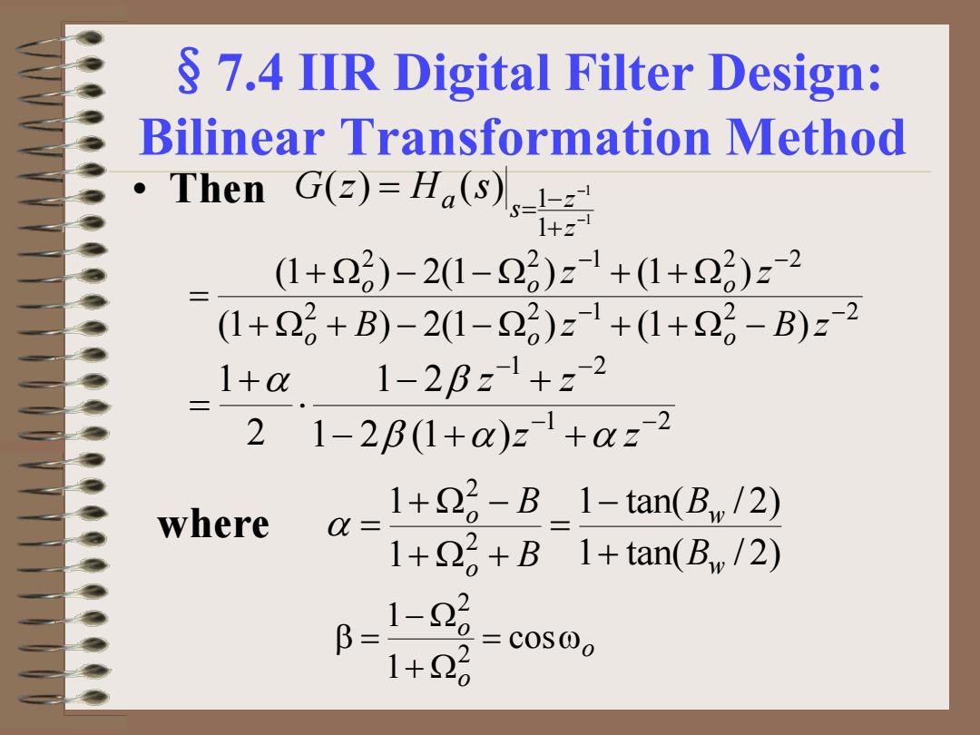
§7.4 IIR Digital Filter Design: Bilinear Transformation Method • Then 1 1 1 1 ( ) ( ) − − + − = = z z s a G z H s 2 2 1 2 2 2 2 1 2 2 (1 ) 2(1 ) (1 ) (1 ) 2(1 ) (1 ) − − − − + Ω + − − Ω + + Ω − + Ω − − Ω + + Ω = B z B z z z o o o o o o 1 2 1 2 1 2 (1 ) 1 2 2 1 − − − − − + + − + ⋅ + = z z z z β α α α β 1 tan( / 2) 1 tan( / 2) 1 1 2 2 w w o o B B B B + − = + Ω + + Ω − α = o o o = ω + Ω − Ω β = cos 1 1 2 2 where