To conclude -1 ●●● ●●●● ●●●●● Frequency synthesis Methods ●●●0 ●●●●0 provide a large number of precisely controlled frequency derived 25.26,27.28. form a stable oscillator. ⊙ ×10 30 MHz 29,.30.31.32. 33.34.35 3 MHz MHz 1.Direct Synthesis TXCO 1 MHz +3 Tunable 2 MHz BPF ×2 Drawback:complicated;massive; 3 MHz 1.2.3.4.5 ×3 MHz expensive;inflexible 4 MHz 2.Direct Digital Synthesis x5 5 MHz (Digital Look-up Synthesis) Vo=Asin( 2对 Phase Sin 0 DAC accumulator table (N bit) (M bit) At present: W Frequency Frequency resolution control Clock 1Hz Settling-time 10ns 1
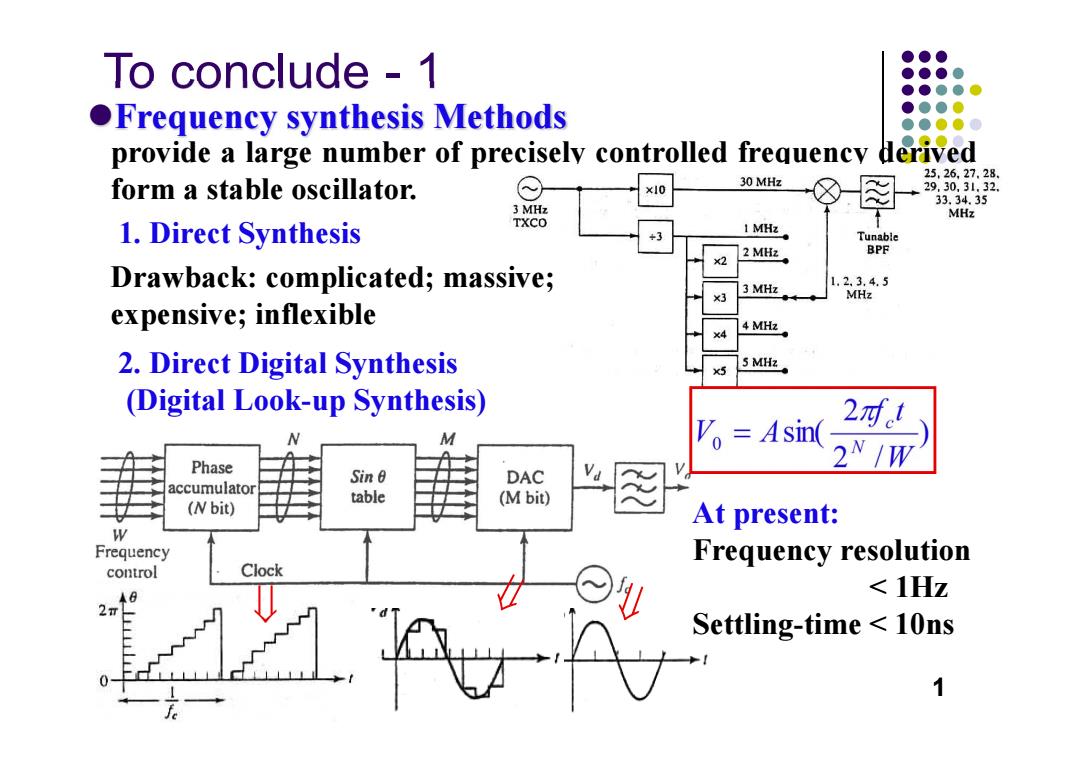
To conclude - 1 Frequency synthesis Methods provide a large number of precisely controlled frequency derived form a stable oscillator. 1. Direct Synthesis Drawback: complicated; massive; expensive; inflexible 2. Direct Digital Synthesis (Digital Look-up Synthesis) At present: Frequency resolution < 1Hz Settling-time < 10ns 1
●●● To conclude -1 ●●●● Voltage ●●●●心 Phase Loop Loop controlled ●●●0 ●Phase-locked detector amplifier filter oscillator ●●●●0 ●●●● loops Ud(t) Uc(t) Output ●●●● 听% ●● Reference oscillator Frequency divider ÷W VCO 6=217.5 LPF -222.5MHz Multiplier ●Practical 图 fou=4(-N52) ×4 synthesizer 五=7.5kHz DDS circuits BPF 斤=228.02250MHz Programmable divider 737<N<1402 detector ampuitier tilter vCO fo ●Fractional fout Reference phase-locked oscillator Divider +N loops or +(W+I) Adder/ Division accumulator ratio 2
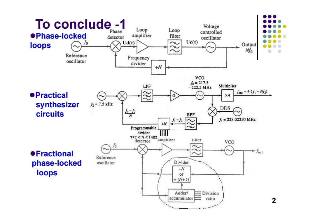
To conclude -1 Phase-locked loops Practical synthesizer circuits Fractional phase-locked loops 2
To conclude-2 Flicker Random phase variation Oscillator phase noise Noise £(fm)= Discrete spurious P Divided into Thermal signal and shot (1)Spurs--Oscillator harmonics, Noise mixer products,leakage of the reference fo signals,spurious frequencies generated by the phase detector,supply. (2)Random fluctuations--thermal and other noise sources Leeson's Model for oscillator phase noise ASp(w) So(@)=kZiF 1+ S(w) S.(w) fi<f (high O) Flicker NoiseP f>f(low e) /f @n=00/2Q,half-power bandwidth KToF of the resonator Po Thermal /Shot kToFIPo kToFIPo Noise 6 Idealized power spectral fo fa fa density of amplifier noise. S(0):S,m)/1·以(@ Maximum phase noise of a receiver Problem 8.17,page 287 (f )=C(dBm)-I(dBm)-S(dB)-101g B (dBc/Hz) 3
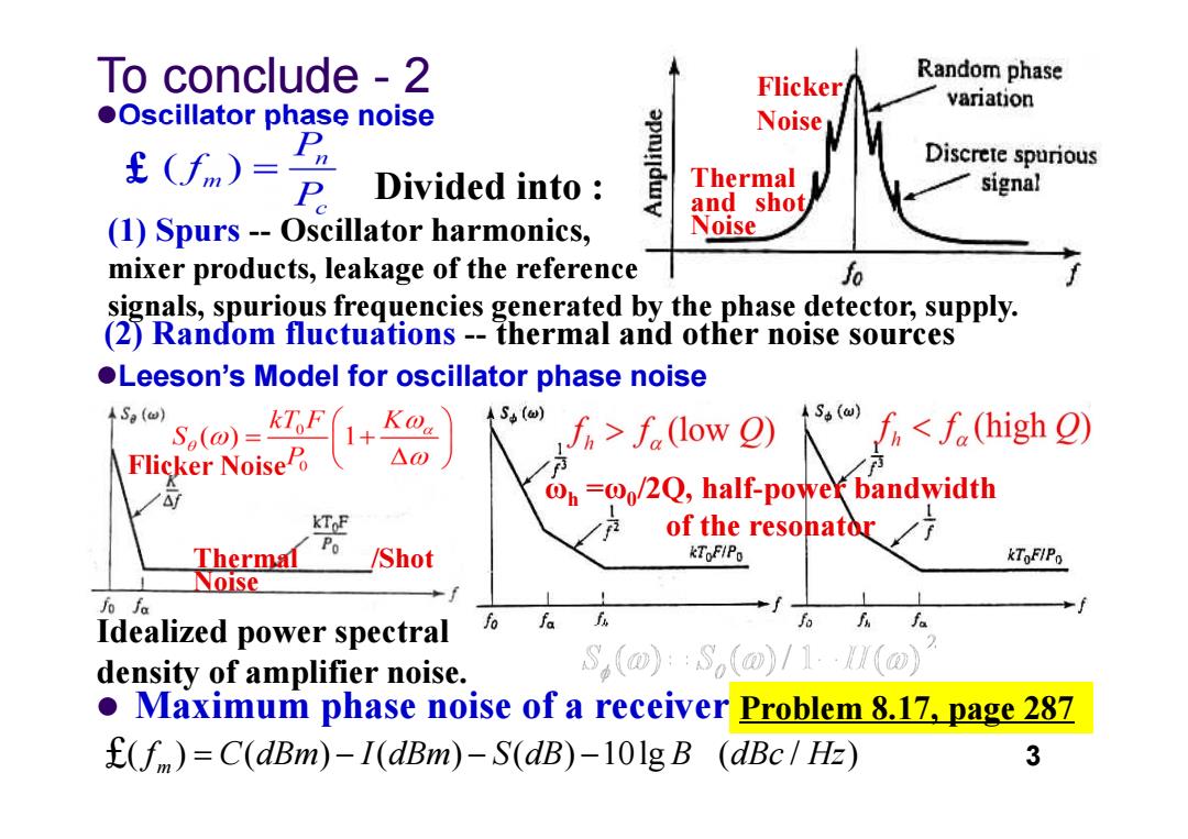
Oscillator phase noise To conclude - 2 Flicker Noise Thermal and shot Noise Divided into : (1) Spurs -- Oscillator harmonics, mixer products, leakage of the reference signals, spuriousfrequencies generated by the phase detector, supply. (2) Random fluctuations -- thermal and other noise sources £ Leeson’s Model for oscillator phase noise Flicker Noise Thermal /Shot Noise Idealized power spectral density of amplifier noise. ωh =ω0/2Q, half-power bandwidth of the resonator Maximum phase noise of a receiver £( ) ( ) ( ) ( ) 10lg ( / ) 3 mf C dBm I dBm S dB B dBc Hz Problem 8.17, page 287
●●● DO D● RF RF Baseband data in Modulator Upconverter RF stage Radio transmitter RF RF IF Baseband data out RF stage Down converter Demodulator Radio receiver 5
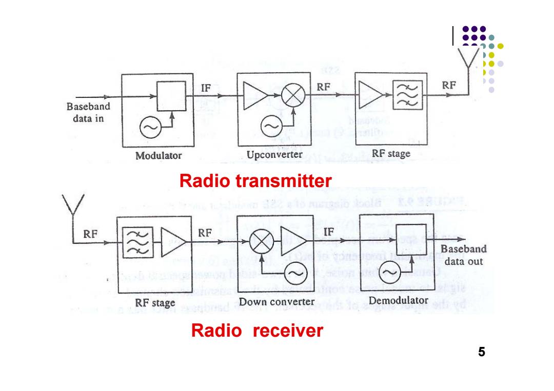
Radio transmitter Radio receiver 5
●●● ●●●● ●●● ●●●0 Microwave and RF Design of 0●●●● e●●0 ●●●● ● ● Wireless Systems Chapter 9 Modulation Techniques 调制技术 Dr.Xian Qi Lin 6
Modulation Techniques 调制技术 Microwave and RF Design of Wireless Systems Chapter 9 Dr. Xian Qi Lin 6