
2.In the introduction,it is stated that piles transfer load to the nng grour nd.State how this is achieved. 3.Piles are made ut of differentmaterials.In short state the advantages and disadvantages of these materials. 4.Piles can be referred as displacement and non-displacement piles.State the differences and the similarities of these piles 5.Piles can be classified as end-bearing piles cohesive or friction les. cnesined aspored or diven shediferences 6. and similarity of thes LOAD ON PILES 2.1 Introduction This section of the guide is divided into two parts.The first part gives brief bas c pile arrangements while part two deals ad distribution Piles can be arranged in a number of ways so that they can support load imposed on them.Vertical piles can be designed to carry vertical loads as well as lateral loads.If required,vertical piles can be combined with raking piles to support horizontal and vertical forces. often,if a pile group is subjected to vertical force,then the calculation of oad distribution on single pile that is member of the group is assumed to be the total load divided by the number of piles in the group.However if a group of piles is subjected to lateral load or eccentric vertical load or combination of should be taken into account duri sidere d to be part of the bjetive:n theirstpar ofisseciiingof pilesw limited numberof piles subjected to vertical and lateral forces.forces acting centrally or eccentrically,we leamn how these forces are distributed on individual piles. The worked examples are intended to give easy follow through exercise that can help quick understanding of pile design both single and group of piles.In the second part,the comparison made between different methods used in pile
2. In the introduction, it is stated that piles transfer load to the bearing ground. State how this is achieved. 3. Piles are made out of different materials. In short state the advantages and disadvantages of these materials. 4. Piles can be referred as displacement and non-displacement piles. State the differences and the similarities of these piles 5. Piles can be classified as end-bearing piles cohesive or friction piles. Describe the differences and similarity of these piles. 6. Piles can be classified as bored or driven state the differences. LOAD ON PILES 2.1 Introduction This section of the guide is divided into two parts. The first part gives brief summary on basic pile arrangements while part two deals with load distribution on individual piles. Piles can be arranged in a number of ways so that they can support load imposed on them. Vertical piles can be designed to carry vertical loads as well as lateral loads. If required, vertical piles can be combined with raking piles to support horizontal and vertical forces. often, if a pile group is subjected to vertical force, then the calculation of load distribution on single pile that is member of the group is assumed to be the total load divided by the number of piles in the group. However if a group of piles is subjected to lateral load or eccentric vertical load or combination of vertical and lateral load which can cause moment force on the group which should be taken into account during calculation of load distribution. In the second part of this section, piles are considered to be part of the structure and force distribution on individual piles is calculated accordingly. Objective: In the first part of this section, considering group of piles with limited number of piles subjected to vertical and lateral forces, forces acting centrally or eccentrically, we learn how these forces are distributed on individual piles. The worked examples are intended to give easy follow through exercise that can help quick understanding of pile design both single and group of piles. In the second part, the comparison made between different methods used in pile
methods while exercising pile designing. Learning outcome When students complete this section,they will be able to: Calculate load distribution on group of piles consist of vertical piles cted to vertical Clte toad stribution on vertically aanged piles subiected to lateral and vertical forces. Calculate load distribution on vertical and raking piles subjected to horizontal and eccentric vertical loads. Calculate load distribution on sy 2.2 Pile arrangement Normally,pile foundations consist of pile cap and a group of piles.The pile cap distributes the applied load to the individual piles which in tum.transfer the load to the bearin g ground.The individual piles are spaced and connected to the pile cap or tie beams and trimmed in order to connectthe pile to the structure at cut-off level,and depending on the type of structure and eccentricity of the load,they can be arranged in different patterns.Figure 2.1 bellow illustrates the three basic formation of pile groups
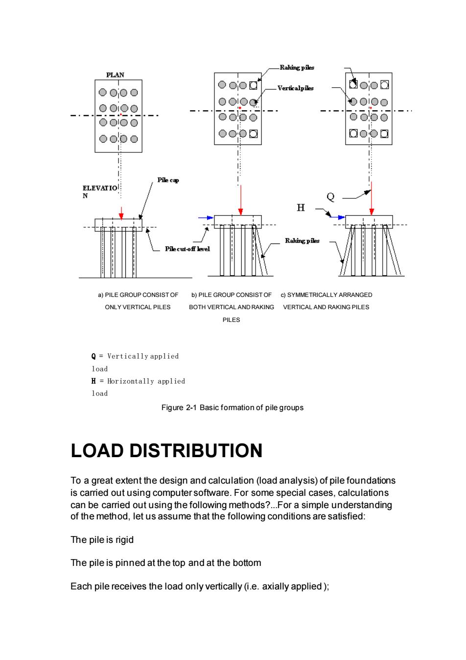
design will enable students to appreciate the theoretical background of the methods while exercising pile designing. Learning outcome When students complete this section, they will be able to: • Calculate load distribution on group of piles consist of vertical piles subjected to eccentric vertical load. • Calculate load distribution on vertically arranged piles subjected to lateral and vertical forces. • Calculate load distribution on vertical and raking piles subjected to horizontal and eccentric vertical loads. • Calculate load distribution on symmetrically arranged vertical and raking piles subjected to vertical and lateral forces 2.2 Pile arrangement Normally, pile foundations consist of pile cap and a group of piles. The pile cap distributes the applied load to the individual piles which, in turn,. transfer the load to the bearing ground. The individual piles are spaced and connected to the pile cap or tie beams and trimmed in order to connect the pile to the structure at cut-off level, and depending on the type of structure and eccentricity of the load, they can be arranged in different patterns. Figure 2.1 bellow illustrates the three basic formation of pile groups
一Rakingpiles PLAN ooog oioa 0000 001Oo 6666 ao Pile ca H PILE GROUP CONSIS SYMMETRICALLY ARRA GE ONLY VERTICAL PILES BOTH VERTICAL AND RA VERTICAL AND RAKING PILES PILES Q=Vertically applied load H=Horizontally applied load Figure 2-1 Basic fomation of pile groups LOAD DISTRIBUTION To a great extent the design and calculation(load analysis)of pile foundations is carried out using computer software.For some special cases,calculations can be carried out using the following methods?...For a simple understanding of the method,let us assume that the following conditions are satisfied: The pile is rigid The pile is pinned at the top and at the bottom Each pile receives the load only vertically(i.e.axially applied):
a) PILE GROUP CONSIST OF ONLY VERTICAL PILES b) PILE GROUP CONSIST OF BOTH VERTICAL AND RAKING PILES c) SYMMETRICALLY ARRANGED VERTICAL AND RAKING PILES Q = Vertically applied load H = Horizontally applied load Figure 2-1 Basic formation of pile groups LOAD DISTRIBUTION To a great extent the design and calculation (load analysis) of pile foundations is carried out using computer software. For some special cases, calculations can be carried out using the following methods?...For a simple understanding of the method, let us assume that the following conditions are satisfied: The pile is rigid The pile is pinned at the top and at the bottom Each pile receives the load only vertically (i.e. axially applied );
The force P acting on the pile is proportional to the displacement U due to compression P=k.U ????????3.1 Since P=E.A E.A=k.U ??77???????????7?3.2 ??????????3.3 U where. P=vertical load component k=material constant U=displacement E=elastic module of pile material A=cross-sectional area ofpile Figure 3-1 load on single pile
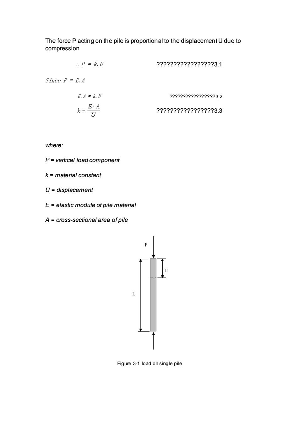
The force P acting on the pile is proportional to the displacement U due to compression P = k.U ?????????????????3.1 Since P = E.A E.A = k.U ?????????????????3.2 ?????????????????3.3 where: P = vertical load component k = material constant U = displacement E = elastic module of pile material A = cross-sectional area of pile Figure 3-1 load on single pile
The length L should not necessarily be equal to the actual length of the pile.In a group of piles fall piles are of thesame material.have samecross-sectionlarea and equal the value of k is piles in thegroup Let us assume that the vertical load on the pile group results in vertical,lateral and torsion movements.Further,let us assume that for each pile in the group.these movements are small and are caused by the component of the vertical load experienced by the pile.The formulae in the forthcoming sections which are used in the calculation of pile loads.are based on these assumptions. 3.1 Pile foundations:vertical piles only Here the pile cap is causing the vertical compression U.whose magnitude is equal for all members of the group.If Q(the vertical force acting on the pile group)is applied at the neutral axis of the pile group.then the force on a single pile will be as follows: 7??7????????7??7?3.4 where: P.=vertical component of the load on any pile from the resultant load Q n number of vertical piles in the group(see fig3.4) Q=total vertical load on pile group If the same group of piles are subjected to an eccentric load Q which is causing rotation around axisz(see fig 3.1):then for the pileiat distancefrom axisz U=at9gU=ra9→月=ka9?????????3.5 0is a small angle figure3.4.) P.=force (load on a single pilei U.displacement caused by the eccentric force (load)Q
The length L should not necessarily be equal to the actual length of the pile. In a group of piles, If all piles are of the same material, have same cross-sectional area and equal length L , then the value of k is the same for all piles in the group. Let us assume that the vertical load on the pile group results in vertical, lateral and torsion movements. Further, let us assume that for each pile in the group, these movements are small and are caused by the component of the vertical load experienced by the pile. The formulae in the forthcoming sections which are used in the calculation of pile loads, are based on these assumptions. 3.1 Pile foundations: vertical piles only Here the pile cap is causing the vertical compression U, whose magnitude is equal for all members of the group. If Q (the vertical force acting on the pile group) is applied at the neutral axis of the pile group, then the force on a single pile will be as follows : ?????????????????3.4 where: Pv = vertical component of the load on any pile from the resultant load Q n = number of vertical piles in the group (see fig3.4) Q = total vertical load on pile group If the same group of piles are subjected to an eccentric load Q which is causing rotation around axis z (see fig 3.1); then for the pile i at distance rxi from axis z: ?????????????????3.5 is a small angle tan see figure3.4.) Pi = force (load on a single pile i Ui = displacement caused by the eccentric force (load) Q