EXAMPLE 4.4 (0.5-0.0195(0.866)MPa or 48.3 In order to avoid transverse tensile failure, longitudinal tensile failure 18 the AS/3501 data in table 2.2 and table 4.1,we find that in order to avoid where only the tensile strengths have been used because o,is positive.Using x<sin0 cos0 Ox< 9.A! sin20-V21 cos20 号 cos20-Vi2sin20 Ox <205MPa relations in equation(4.1),the Maximum Strain Criterion(eq.[4.5])becomes Assuming linear elastic behavior up to failure and using the stress-strain (eqs.[4.3])in the lamina stress-strain equations(2.24)and(2.25),we find that in terms of the applied stress,o.Upon substituting the stress transformation Solution.First,the strains along the principal material axes must be found AS/3501 carbon/epoxy and the angle 0=30. for off-axis loading of the unidirectional lamina in figure 4.4 if the material is Using the Maximum Strain Criterion,determine the uniaxial failure stress, yield approximately the same result.This is not always true,however. Solving for p,we find that p=1.61 MPa.Thus,for this case,the two criteria Principles of Composite Material Mechanics failure strain,which is typical for ceramic matrix composites.Amodel based shows the case where the fiber failure strain is greater than the matrix- for this case by Kelly and Davies [50]will be summarized here.Figure 4.9(b) strain,en),which is typical for many polymer matrix composites.A model matrix failure strain,em(,is assumed to be greater than the fiber failure materials are shown in figure 4.9(a)and figure 4.9(b).In figure 4.9(a),the and the representative stress-strain curves for fiber,matrix,and composite can be developed from the rule of mixtures for longitudinal stress(eq.[3.191) Simple micromechanics models for composite longitudinal tensile strength 4.3.1 Longitudinal Strength strengths and compressive strengths. necessary to develop different micromechanics models for tensile differences between tensile and compressive modes of failure make it and statistical methods must be used for accurate analysis.In addition, variability of strength in reinforcing fibers alone may be quite significant, much greater.For example,as shown in figure 4.8 from ref.[491,the sites of such stress and strain concentrations,so the effect on strength is ulus theories.On the other hand,material failure is often initiated at the reduced due to the smoothing effect of integration in the effective mod- the effects of such local stress and strain perturbations on stiffness are turbations in the stress and strain distributions.As shown in chapter 3, by material and geometric nonhomogeneity and the resulting local per- those for stiffness,because the strength is affected more than the stiffness should not expect such simple models for strength to be as accurate as to micromechanical modeling of lamina strength will be described.We In this section,the use of elementary mechanics of materials approaches Micromechanics Models for Lamina Strength the validity of the various failure criteria [27,28]. the failure stress may be different.The off-axis tensile test has been used to check that for compressive loading or other loading angles both the mode of failure and the applied stress at failure is =143 MPa.The reader is encouraged to check Thus,according to the Maximum Strain Criterion,the mode of failure is shear,and G*50.8860 621 and in order to avoid shear failure, MPa or <143MPa Strength of a Continuous Fiber-Reinforced Lamina
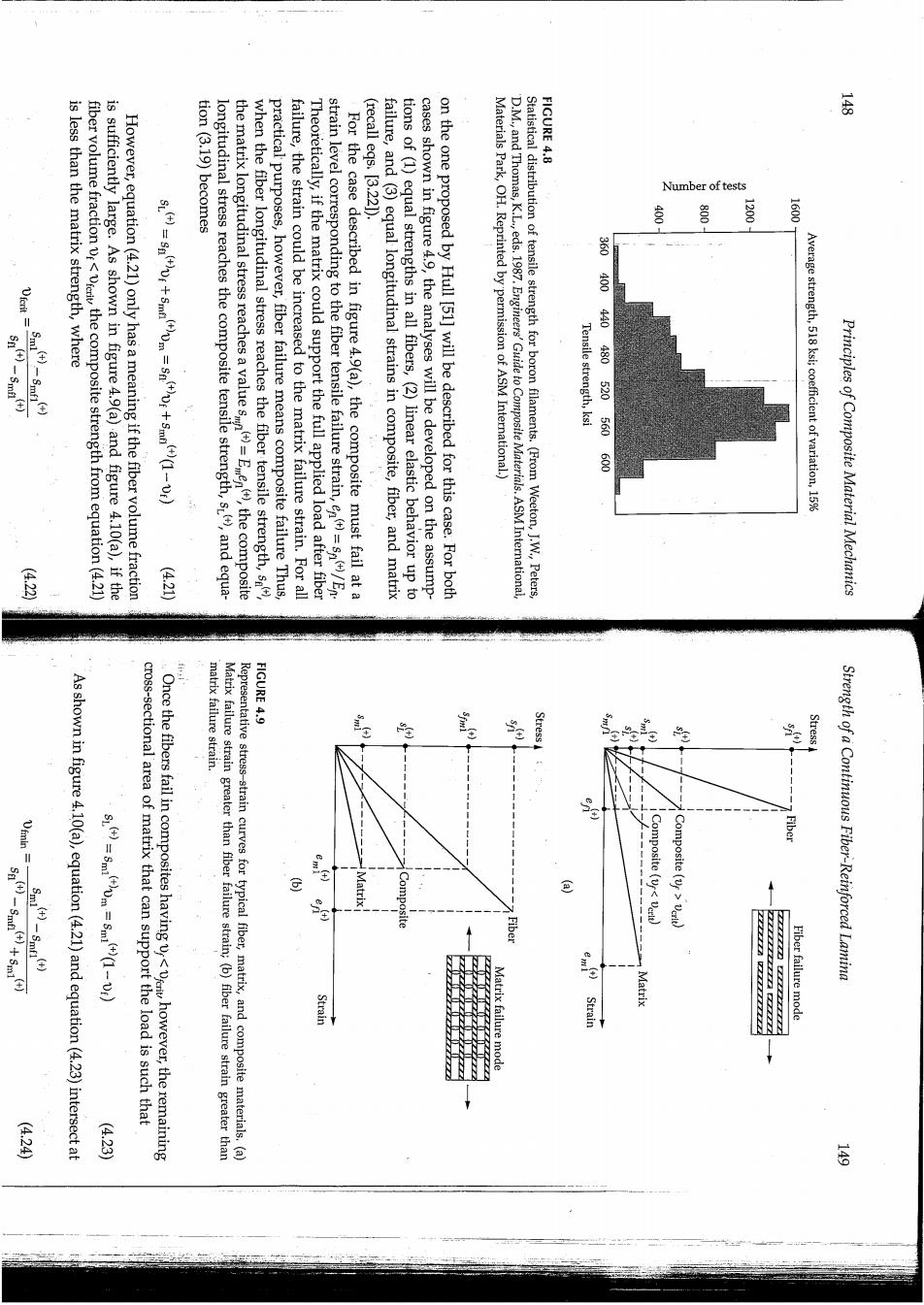
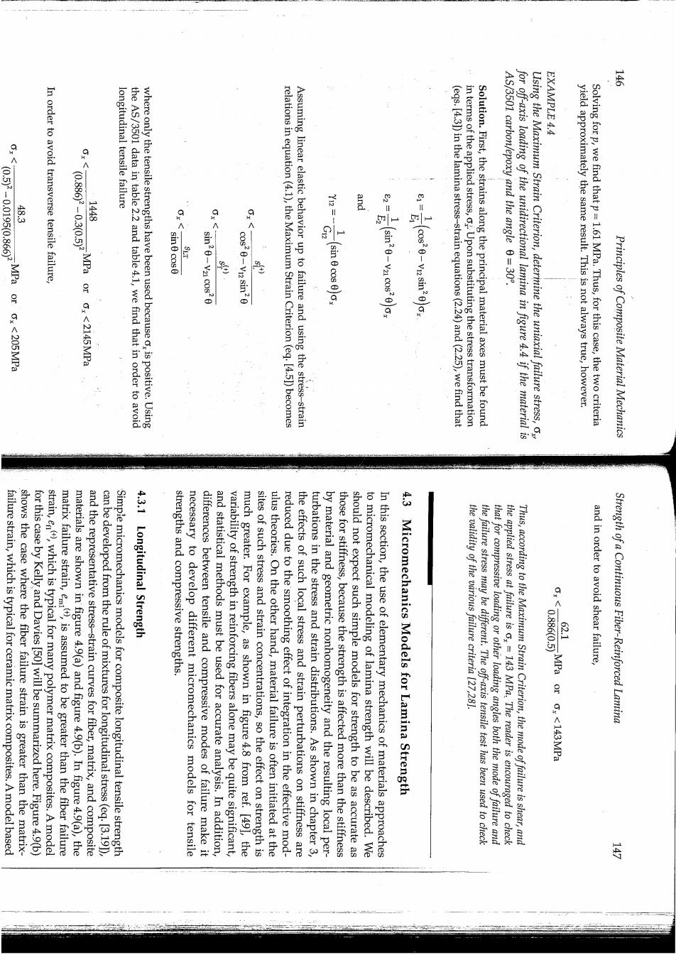
FIGURE 4.8 云 is less than the matrix strength,where Number of tests fiber volume fraction vr<verit the composite strength from equation(4.21 is sufficiently large.As shown in figure 4.9(a)and figure 4.10(a),if the (recall egs.[3.221). However,equation(4.21)only has a meaning if the fiber volume fraction tion(3.19)become longitudinal stress reaches the composite tensile strength,s,and equa- the matrix longitudinal stress reaches a value sm when the fiber longitudinal stress reaches the fiber tensile strength,s practical purposes,however,fiber failure means composite failure Thus, failure,the strain could be increased to the matrix failure strain.For all Theoretically,if the matrix could support the full applied load after fiber strain level corresponding to the fiber tensile failure strain,e=s/En For the case described in figure 4.9(a),the composite must fail at a failure,and(3)equal longitudinal strains in composite,fiber,and matrix tions of (1)equal strengths in all fibers,(2)linear elastic behavior up to cases shown in figure 4.9,the analyses will be developed on the assump- on the one proposed by Hull [51]will be described for this case.For both Materials Park,OH.Reprinted by permission of ASM International) D.M.,and Thomas,K.L eds.1987.Engineers'Guide to Composite Materials.ASM International, Statistical distribution of tensile strength for boron filaments.(From Weeton,J.W.,Peters, 营 凳 1200 1600 860 400 Tensile strength,ksi 440480520560600 Average strength,518 ksi;coefficient of variation,15% ()=Een),the composite Principles of Composite Material Mechanics (4210 matrix failure strain. FIGURE 4.9 Stress As shown in figure 4.10(a),equation(4.21)and equation(4.23)intersect at cross-sectional area of matrix that can support the load is such that Once the fibers fail in composites having however,the remaining Matrix failure strain greater than fiber failure strain;(b)fiber failure strain greater than Representative stress-strain curves for typical fiber,matrix,and composite materials.(a) Composite (< Fiber Composite (vf verit) Strength of a Continuous Fiber-Reinforced Lamina Strain Matrix er failure mode (424 4·23
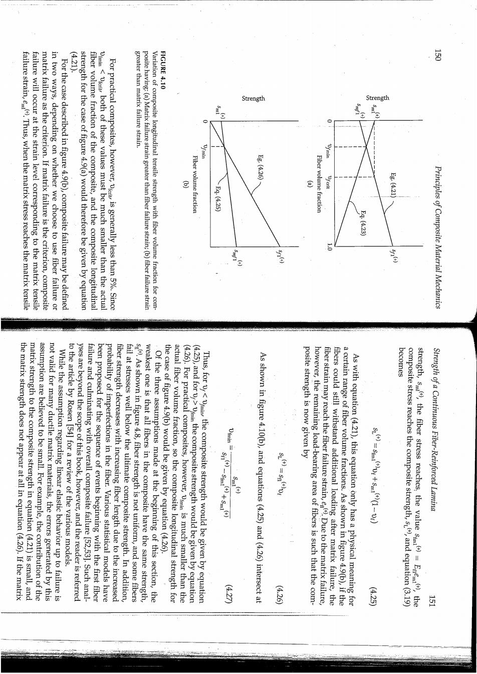
421. FIGURE 4.10 Strength Strength failure strain,e).Thus,when the matrix stress reaches the matrix tensile failure will occur at the strain level corresponding to the matrix tensile matrix failure as the criterion.If matrix failure is the criterion,composite in two ways,depending on whether we choose to use fiber failure or For the case described in figure 4.9(b),composite failure may be defined strength for the case of figure 4.9(a)would therefore be given by equation fiber volume fraction of the composite,and the composite longitudinal vmin<vrcit,both of these values must be much smaller than the actual For practical composites,however,ri is generally less than 5%.Since greater than matrix failure strain. Posite having:(a)Matrix failure strain greater than fiber failure strain;(b)fiber failure strain Variation of composite longitudinal tensile strength with fiber volume fraction for com- Fiber volume fraction E8:(420 E9.(425 Fiber volume fraction g.M21 E4.(A23 Principles of Composite Material Mechanics becomes the matrix strength does not appear at all in equation(4.26).If the matrix matrix strength to the composite strength in equation(4.21)is small,and assumption are believed to be small.For example,the contribution of the not valid for many ductile.matrix materials,the errors generated by this While the assumption regarding linear elastic behavior up to failure is yses are beyond the scope of this book,however,and the reader is referred to the article by Rosen [54]for a review of the various models. been proposed for the sequence of events beginning with the first fiber failure and culminating with overall composite failure [52,53].Such anal- probability of imperfections in the fiber.Various statistical models have fiber strength decreases with increasing fiber length due to the increased sa).As shown in figure 4.8,fiber strength is not uniform,and some fibers fail at stresses well below the ultimate composite strength.In addition, weakest one is that all fibers in the composite have the same strength, Of the three assumptions made at the beginning of this section,the the case of figure 4.9(b)would be given by equation(4.26). actual fiber volume fraction,so the composite longitudinal strength for (4.25),and for v>vmmin the composite strength would be given by equation (4.26).For practical composites,however,vmin is much smaller than the Thus,forv the composite strength would be given by equation As shown in figure 4.10(b),and equations(4.25)and(4.26)intersect at posite strength is now given by however,the remaining load-bearing area of fibers is such that the com- fiber strain may reach the fiber failure strain,e)Due to the matrix failure, fibers could still withstand additional loading after matrix failure,the a certain range of fiber volume fractions.As shown in figure 4.9(b),if the As with equation(4.21),this equation only has a physical meaning for strength,s(),the fiber stress reaches,the value sm()=Enemi(),the composite stress reaches the composite strength,sL(),and equation(3.19) Strength of a Continuous Fiber-Reinforced Lamina (420 (426 (425) 三
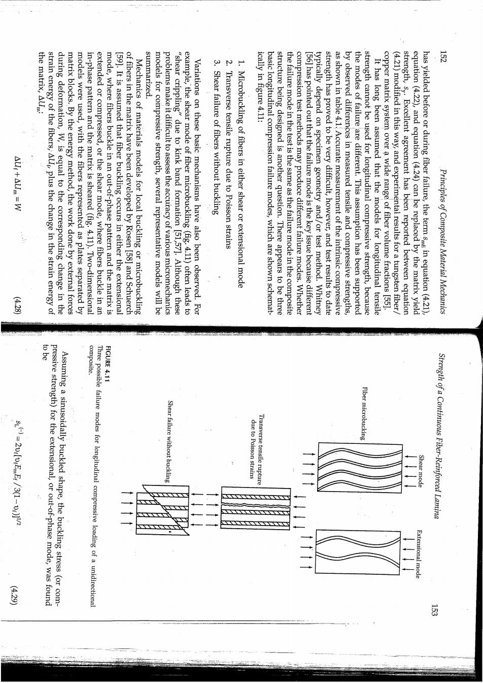
the matrix,AUm: summarized. AUr+Aum =W strain energy of the fibers,Als plus the change in the strain energy of during deformation,W,is equal to the corresponding change in the matrix blocks.By the energy method,the work done by external forces models were used,with the fibers represented as plates separated by in-phase pattern and the matrix is sheared (fig.4.11).Two-dimensional extended or compressed,or the shear mode,where fibers buckle in an mode,where fibers buckle in an out-of-phase pattern and the matrix is 159].It is assumed that fiber buckling occurs in either the extensional of fibers in the matrix have been developed by Rosen [58]and Schuerch Mechanics of materials models for local buckling or microbuckling models for compressive strength,several representative models will be problems make it difficult to assess the accuracy of various micromechanics "shear crippling"due to kink band formation [51,57].Although these example,the shear mode of fiber microbuckling (fig.4.11)often leads to Variations on these basic mechanisms have also been observed.For 3.Shear failure of fibers without buckling 2.Transverse tensile rupture due to Poisson strains 1.Microbuckling of fibers in either shear or extensional mode ically in figure 4.11: basic longitudinal compression failure modes,which are shown schemat- structure being designed is another question.There appears to be three the failure mode in the test is the same as the failure mode in the composite compression test methods may produce different failure modes.Whether [56]has pointed out that the failure mode is the key issue because different typically depend on specimen geometry and/or test method.Whitney strength has proved to be very difficult,however,and test results to date as shown in table 4.1.Accurate measurement of the intrinsic compressive by observed differences in measured tensile and compressive strengths, the modes of failure are different.This assumption has been supported strength cannot be used for longitudinal compressive strength,because It has long been assumed that the models for longitudinal tensile copper matrix system over a wide range of fiber volume fractions [551. (4.21)modified in this way,and experimental results for a tungsten fiber strength,s,.Excellent agreement has been reported between equation equation (4.22),and equation(4.24)can be replaced by the matrix yield has yielded before or during fiber failure,the term smf in equation(4.21) Principles of Composite Material Mechanics (423) pressive strength)for the extensional,or out-of-phase mode,was found to be composite. FIGURE 4.11 Assuming a sinusoidally buckled shape,the buckling stress (or com- Three possible failure modes for longitudinal compressive loading of a unidirectional Shear failure without buckling Transverse tensile rupture Fiber microbucking due to Poisson strains Shear mode Strength of a Continuous Fiber-Reinforced Lamina Extensional mode 星 每
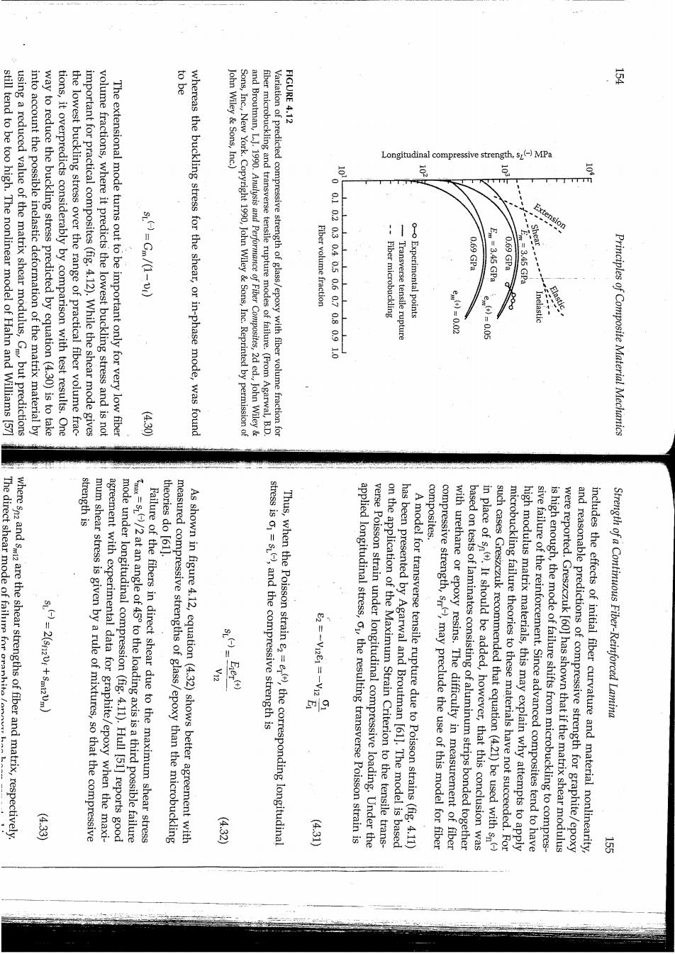
to be FIGURE 4.12 still tend to be too high.The nonlinear model of Hahn and Williams [57] using a reduced value of the matrix shear modulus,Gm but predictions into account the possible inelastic deformation of the matrix material by way to reduce the buckling stress predicted by equation(4.30)is to take tions,it overpredicts considerably by comparison with test results.One the lowest buckling stress over the range of practical fiber volume frac- important for practical composites(fig.4.12).While the shear mode gives volume fractions,where it predicts the lowest buckling stress and is not John Wiley Sons,Inc.) The extensional mode turns out to be important only for very low fiber whereas the buckling stress for the shear,or in-phase mode,was found Sons,Inc.New York.Copyright 1990,John Wiley &Sons,Inc.Reprinted by permission of and Broutman,L.J.1990.Analysis and Performance of Fiber Composites,2d ed.John Wiley& fiber microbuckling and transverse tensile rupture modes of failure.(From Agarwal,B.D. Variation of predicted compressive strength of glass/epoxy with fiber volume fraction for Longitudinal compressive strength,s()MPa m Exte S1.()=Gm/(1-Di) Fiber volume fraction 71020804050607080910 Fiber microbuckling Transverse tensile rupture 0.69 GPa Em =3.45 GPa 0.69 GPa 7-3.45GPa 888 Principles of Composite Material Mechanics (4.30 strength is where sand are the shear strengths of fiber and matrix,respectively. The direct shear mode of failure for oranhit/ theories do [611. composites S)=2(sr12V1+5m12Vm) mum shear stress is given by a rule of mixtures,so that the compressive mode under longitudinal compression(fig.4.11).Hull [51]reports good agreement with experimental data for graphite/epoxy when the maxi- Failure of the fibers in direct shear due to the maximum shear stress =s/2 at an angle of 45 to the loading axis is a third possible failure measured compressive strengths of glass/epoxy than the microbuckling As shown in figure 4.12,equation(4.32)shows better agreement with stress is o1=sL,and the compressive strength is Thus,when the Poisson strain e2=er),the corresponding longitudinal applied longitudinal stress,o,the resulting transverse Poisson strain is on the application of the Maximum Strain Criterion to the tensile trans- verse Poisson strain under longitudinal compressive loading.Under the has been presented by Agarwal and Broutman [61].The model is based A model for transverse tensile rupture due to Poisson strains(fig.4.11) compressive strength,s,may preclude the use of this model for fiber with urethane or epoxy resins.The difficulty in measurement of fiber in place of s).It should be added,however,that this conclusion was based on tests of laminates consisting of aluminum strips bonded together microbuckling failure theories to these materials have not succeeded.For such cases Greszczuk recommended that equation (4.21)be used with s sive failure of the reinforcement.Since advanced composites tend to have high modulus matrix materials,this may explain why attempts to apply is high enough,the mode of failure shifts from microbuckling to compres- were reported.Greszczuk [60]has shown that if the matrix shear modulus includes the effects of initial fiber curvature and material nonlinearity, and reasonable predictions of compressive strength for graphite/epoxy Strength of a Continuous Fiber-Reinforced Lamina (4.33 (4·32) (4交1