s 3776. 1965. posite materials.AFML-TR-67-423. 31.Halpin,J.C.and Tsai,S.W.1969.Effects of environmental factors on com- proved bounds on effective properties.Applied Mechanics Reviews,44(2), Torquato,S.1991.Random heterogeneous media:microstructure and im- materials.Journal of Applied Mechanics,31,223-232.Errata,p.219 (March 29.Hashin,Z.and Rosen,B.W.1964.The elastic moduli of fiber reinforced actions of AIME,218,36-41. 28.Paul,B.1960.Prediction of elastic constants of multi-phase materials.Trans- cells.Applied Mechanics Reviews,42(7),193-221. Aboudi,J.1989.Micromechanical analysis of composites by the method of Principles of Composite Material Mechanics 1 Lamina the effective strengths s),s,s,and s and the corresponding values of the volume-averaged stresses that cause failure of the lamina under these same simple states of stress.The stress-strain curves in figure 4.1 show the graphical interpretation of these simple states of stress, approach,the"effective strengths"of the lamina may be defined as ultimate associated with the lamina principal material axes.Using a similar ina stresses to the volume-averaged lamina strains [recall equation(2.7)to equation (2.9)1,are defined by simple uniaxial or shear stress conditions tive moduli."The effective moduli,which relate the volume-averaged lam- relationships for the orthotropic lamina are simplified by the use of"effec- Interlaminar strengths will be discussed in chapter 7 and chapter 9. As shown in chapters 2 and chapter 3,the linear elastic stress-strain as are several micromechanical models for predicting the lamina strengths. strengths under off-axis or multiaxial loading are discussed in this chapter, TThe relationships among these five lamina strengths and the allowable lamina lamina strengths form the basis of a simplified lamina strength analysis, which will,in turn,be used later in a simplified laminate strength analysis. the principal material axes is still another independent property.These five that will be explained later.The in-plane shear strength sr associated with the corresponding tensile strengths s)and,s),and the transverse tensile strength s is typically the smallest of all the lamina strengths for reasons strengths s)and s,associated with these directions may be different from greater than the transverse strength,s In addition,the compressive longitudinal strength of the continuous fiber-reinforced lamina,s,is much chapter 1,the strength of a composite is derived from the strength of the fibers,but this strength is highly directional in nature.For example,the analysis of composite strength is more difficult than the analysis of elastic behavior,which was discussed in chapter 2 and chapter 3.As shown in Because of the variety of failure modes that can occur in composites,the Introduction Strength of a Continuous Fiber-Reinforced
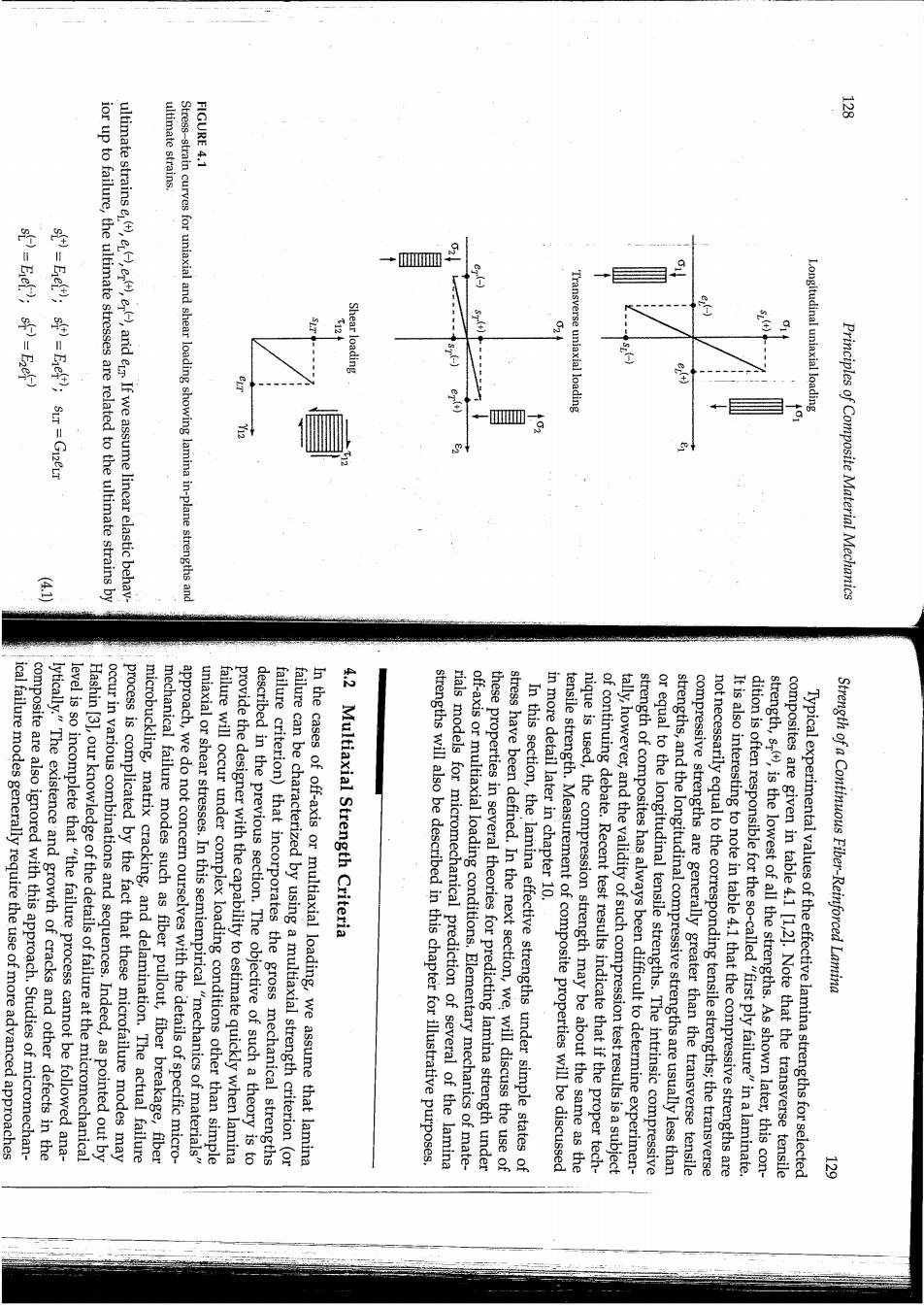
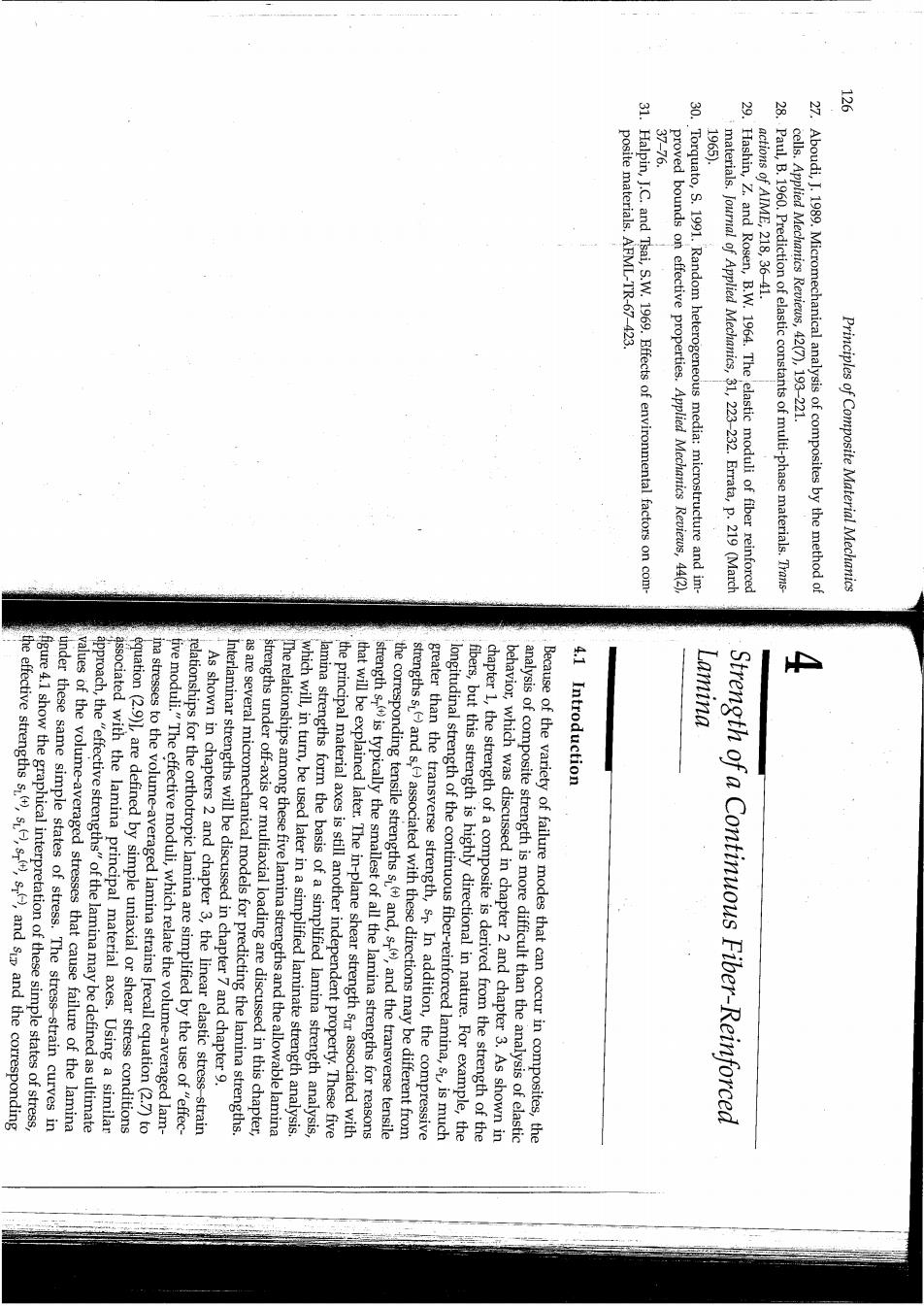
ultimate strains. FIGURE 4.1 oD.号号 ior up to failure,the ultimate stresses are related to the ultimate strains by ultimate strains e,e,e),arid er If we assume linear elastic behav- Stress-strain curves for uniaxial and shear loading showing lamina in-plane strengths and W 9 Shear loading Longitudinal uniaxial loading Principles of Composite Material Mechanics composite are also ignored with this approach.Studies of micromechan- ical failure modes generally require the use of more advanced approaches lytically."The existence and growth of cracks and other defects in the Hashin [3],our knowledge of the details of failure at the micromechanical level is so incomplete that "the failure process cannot be followed ana- microbuckling,matrix cracking,and delamination.The actual failure process is complicated by the fact that these microfailure modes may occur in various combinations and sequences.Indeed,as pointed out by mechanical failure modes such as fiber pullout,fiber breakage,fiber approach,we do not concern ourselves with the details of specific micro- uniaxial or shear stresses.In this semiempirical"mechanics of materials" failure will occur under complex loading conditions other than simple described in the previous section.The objective of such a theory is to provide the designer with the capability to estimate quickly when lamina failure criterion)that incorporates the gross mechanical strengths In the cases of off-axis or multiaxial loading,we assume that lamina failure can be characterized by using a multiaxial strength criterion (or 4.2 Multiaxial Strength Criteria rials models for micromechanical prediction of several of the lamina strengths will also be described in this chapter for illustrative purposes. off-axis or multiaxial loading conditions.Elementary mechanics of mate- stress have been defined.In the next section,we,will discuss the use of these properties in several theories for predicting lamina strength under In this section,the lamina effective strengths under simple states of in more detail later in chapter 10. nique is used,the compression strength may be about the same as the tensile strength.Measurement of composite properties will be discussed of continuing debate.Recent test results indicate that if the proper tech- tally,however,and the validity of such compression test results is a subject strength of composites has always been difficult to determine experimen- or equal to the longitudinal tensile strengths.The intrinsic compressive strengths,and the longitudinal compressive strengths are usually less than not necessarily equal to the corresponding tensile strengths;the transverse compressive strengths are generally greater than the transverse tensile It is also interesting to note in table 4.1 that the compressive strengths are strength,s(),is the lowest of all the strengths.As shown later,this con- dition is often responsible for the so-called"first ply failure"in a laminate. composites are given in table 4.1 [1,2].Note that the transverse tensile Typical experimental values of the effective lamina strengths for selected Strength of a Continuous Fiber-Reinforced Lamina 三
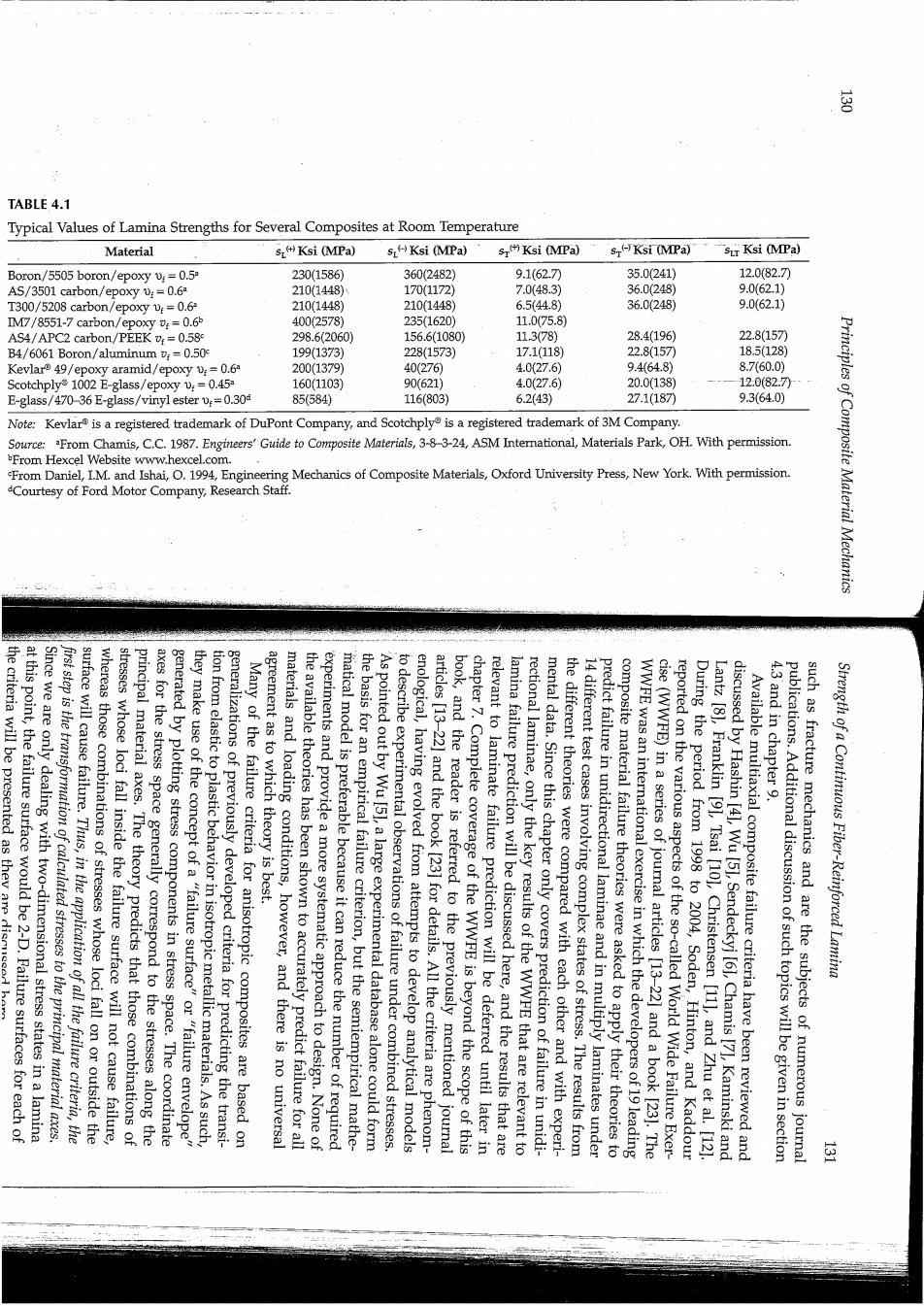
TABLE 4.1 Typical Values of Lamina Strengths for Several Composites at Room Temperature Material sKsi (MPa) 5LKsi (MPa) s Ksi (MPa) s(-Ksi (MPa) sir Ksi (MPa) Boron/5505 boron/epoxy v:=0.5 230(1586) 360(2482) 9.1(62.7刀 35.0(241) 12.0(82.7) AS/3501 carbon/epoxy :=0.6 210(1448) 170(1172 7.0(48.3) 36.0(248) 9.062.1) T300/5208 carbon/epoxy v:=0.6 210(1448) 210(1448) 6.5(44.8) 36.0(248) 9.0(62.1) IM7/8551-7 carbon/epoxy :=0.65 400(2578) 235(1620) 11.075.8) AS4/APC2 carbon/PEEK =0.58 298.6(2060) 156.6(1080) 11.378) 28.4(196) 22.8(157 B4/6061 Boron/aluminum v;=0.50 199(1373) 228(1573) 17.1(118) 22.8157 18.5(128) Kevlar 49/epoxy aramid/epoxy v:=0.6 200(1379) 40(276) 4.0(27.6) 94648) 8.7(60.0) Scotchply1002 E-glass/epoxy v:=0.45 160(1103) 90(621) 4.0(27.6) 20.0(138) 12:0(82.7月 E-glass/470-36 E-glass/vinyl ester0.30 85(584) 116(803) 6.2(43) 27.1(187 9.3(64.0) Note:Kevlar is a registered trademark of DuPont Company,and Scotchply is a registered trademark of 3M Company. Source:From Chamis,C.C.1987.Engineers'Guide to Composite Materials,3-8-3-24,ASM International,Materials Park,OH With permission. From Hexcel Website www.hexcel.com From Daniel,I.M.and Ishai,.1994,Engineering Mechanics of Composite Materials,Oxford University Press,New York.With permission. Courtesy of Ford Motor Company,Research Staff. Principles of Composite Material Mechanics the criteria will be presented as they are dismede at this point,the failure surface would be 2-D.Failure surfaces for each of Since we are only dealing with two-dimensional stress states in a lamina first step is the transformation of calculated stresses to the principal material axes. surface will cause failure.Thus,in the application of all the failure criteria,the stresses whose loci fall inside the failure surface will not cause failure, whereas those combinations of stresses whose loci fall on or outside the axes for the stress space generally correspond to the stresses along the principal material axes.The theory predicts that those combinations of they make use of the concept of a "failure surface"or "failure envelope" generated by plotting stress components in stress space.The coordinate tion from elastic to plastic behavior in isotropic metallic materials.As such, generalizations of previously developed criteria for predicting the transi- Many of the failure criteria for anisotropic composites are based on the available theories has been shown to accurately predict failure for all materials and loading conditions,however,and there is no universal agreement as to which theory is best. experiments and provide a more systematic approach to design.None of the basis for an empirical failure criterion,but the semiempirical mathe- matical model is preferable because it can reduce the number of required to describe experimental observations of failure under combined stresses. As pointed out by Wu [51,a large experimental database alone could form enological,having evolved from attempts to develop analytical models book,and the reader is referred to the previously mentioned journal articles [13-22]and the book [23]for details.All the criteria are phenom- chapter 7.Complete coverage of the WWFE is beyond the scope of this relevant to laminate failure prediction will be deferred until later in lamina failure prediction will be discussed here,and the results that are rectional laminae,only the key results of the WWFE that are relevant to mental data.Since this chapter only covers prediction of failure in unidi- 14 different test cases involving complex states of stress.The results from the different theories were compared with each other and with experi- predict failure in unidirectional laminae and in multiply laminates under WWFE was an international exercise in which the developers of 19 leading composite material failure theories were asked to apply their theories to cise(WWFE)in a series of journal articles [13-22]and a book [23].The During the period from 1998 to 2004,Soden,Hinton,and Kaddour reported on the various aspects of the so-called World Wide Failure Exer- discussed by Hashin [41,Wu [51,Sendeckyj [61,Chamis [7],Kaminski and Lantz [8],Franklin [9],Tsai [10],Christensen [11],and Zhu et al.[12] Available multiaxial composite failure criteria have been reviewed and 4.3 and in chapter 9. such as fracture mechanics and are the subjects of numerous journal publications.Additional discussion of such topics will be given in section Strength of a Continuous Fiber-Reinforced Lamina 运
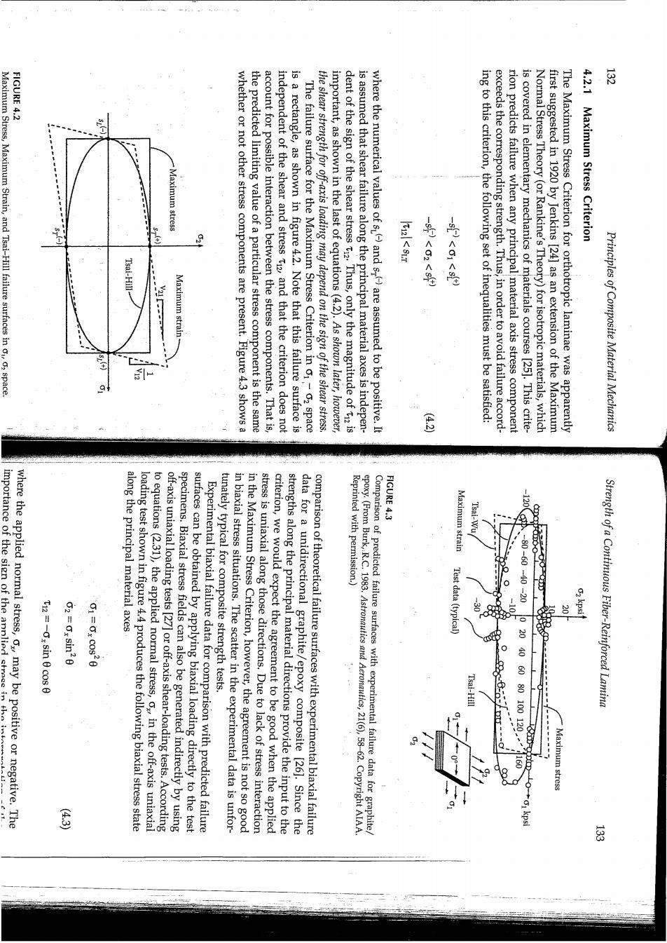
FIGURE 4.2 Maximum Stress,Maximum Strain,and Tsai-Hill failure surfaces in o,o2 space. laximum stress Maximum strain whether or not other stress components are present.Figure 4.3 shows a the predicted limiting value of a particular stress component is the same account for possible interaction between the stress components.That is, independent of the shear and stress t2,and that the criterion does not is a rectangle,as shown in figure 4.2.Note that this failure surface is The failure surface for the Maximum Stress Criterion in 01-02 space the shear strength for off-axis loading may depend on the sign of the shear stress. important,as shown in the last of equations(4.2).As shown later,however, dent of the sign of the shear stress t.Thus,only the magnitude of t2 is is assumed that shear failure along the principal material axes is indepen- where the numerical values of s)and s-)are assumed to be positive.It -s<01<) ing to this criterion,the following set of inequalities must be satisfied: exceeds the corresponding strength.Thus,in order to avoid failure accord- rion predicts failure when any principal material axis stress component is covered in elementary mechanics of materials courses [25].This crite- Normal Stress Theory(or Rankine's Theory)for isotropic materials,which first suggested in 1920 by Jenkins [24]as an extension of the Maximum The Maximum Stress Criterion for orthotropic laminae was apparently 4.2.1 Maximum Stress Criterion Principles of Composite Material Mechanics FIGURE 4.3 where the applied normal stress,ox,may be positive or negative.The importance of the sign of the annlied streee inthe along the principal material axes Maximum strain T12=-0x sin 0 cos 0 2=Ox sin20 to equations (2.31),the applied normal stress,o in the off-axis uniaxial loading test shown in figure 4.4 produces the following biaxial stress state off-axis uniaxial loading tests [27]or off-axis shear-loading tests.According surfaces can be obtained by applying biaxial loading directly to the test specimens.Biaxial stress fields can also be generated indirectly by using Experimental biaxial failure data for comparison with predicted failure in biaxial stress situations.The scatter in the experimental data is unfor- 财。tur stress is uniaxial along those directions.Due to lack of stress interaction in the Maximum Stress Criterion,however,the agreement is not so good strengths along the principal material directions provide the input to the criterion,we would expect the agreement to be good when the applied data for a unidirectional graphite/epoxy composite [26].Since the comparison of theoretical failure surfaces with experimental biaxial failure Reprinted with permission.) Comparison of predicted failure surfaces with experimental failure data for graphite epoxy.(From Burk,R.C.1983.Astronautics and Aeronautics,21(6),58-62.Copyright AIAA Test data(typical -80-60-40-20 - Tsai-Hill 20406080100120 Strength of a Continuous Fiber-Reinforced Lamina Maximum stress 芬

FIGURE 4.5 evaluated 28. FIGURE 4.4 Off-axis shear test of a unidirectional lamina specimen.(a)Positive(b)negative T12 =Txy (cos20-sin20) 02=-2Txy cos0 sin 0 01=2Txy cos0 sin 0 material axes according to equations (2.31): stress,t generates the following biaxial stress state along the principal For the off-axis shear test described in figure 4.5,the applied shear failure versus lamina orientation,0,the various failure criteria can be failure surfaces.By plotting the predicted and measured values of o,at stituted into equations similar to equations (4.2)in order to generate test results here is obvious.These stress components may then be sub- Off-axis uniaxial test of a unidirectional lamina specimen Principles of Composite Material Mechanics failure is 2=-2tx Cos0sin0=-2T.sin For failure by the transverse compressive stress: Txy =1448MPa So the corresponding off-axis shear stress required to produce this mode of 1=27yc0605n8-2700094528m450-7g-5m-1448MPa For failure by the longitudinal tensile stress, Criterion,along with the strength data for T300/5208 from table 4.1,the calculations are as follows: produces longitudinal tension and transverse compression along the prin- cipal material axes.Employing equations(2.31)and the Maximum Stress Solution.From figure 4.5(a),it is seen that a positive off-axis shear stress in figure 4.5(a).Determine the value of the off-axis shear stressthat would cause failure according to the Maximum Stress Criterion. is subjected to a positive off-axis shear stress,at an angle45 as shown An element of an orthotropic lamina made of T300/5208 carbon/epoxy material phases of stress analysis in composite materials. interpretation of tests results as described here;it has implications for all axes shows that the sign of the shear stress makes no difference in that case.The importance of the sign of the shear stress extends beyond the failure.A similar development for pure shear along the principal material shear stress of a certain magnitude could cause a transverse tensile failure, whereas a positive shear stress of the same magnitude would not cause should now be obvious.It is easy to visualize a situation where a negative (table 4.1),the importance of the sign of the applied off-axis shear stress and transverse tension,as shown in figure 4.5(b).Given the fact that the transverse tensile strength is so much lower than the other strengths a negative applied shear stress would produce longitudinal compression would produce longitudinal tension and transverse compression along the principal material axes,as shown in figure 4.5(a).On the other hand, is warranted.For example,if the angle 0=45,equations(4.4)reduce to 1=Ty02=-Yy and t2=0.Thus,a positive applied shear stress,t tation of test results may not be so obvious here,and further discussion The importance of the sign of the applied shear stress in the interpre- Strength of a Continuous Fiber-Reinforced Lamina