structures. figure 7.1 are for laminates consisting of plies of the same material.For by enclosing the set of angles in parentheses.The examples shown in overbar.Sets of ply angles that are repeated in the laminate are identified having an odd number of plies,the center ply angle is denoted by an subscript on the appropriate ply angle.In the case of symmetric laminates plies having the same orientations can be described by using a numerical be described by listing only the ply angles for the top half of the laminate and by using the subscript "s"outside the brackets,and that adjacent shown by the examples in figure 7.1.Note that symmetric laminates can top surface to the bottom surface and enclosed in square brackets,as code is that ply angles,separated by slashes,are listed in order from the orientation code has evolved in the composites literature.The basis of the nations of ply orientations and stacking sequences in laminates,a laminate Because of the need for adequate description of many possible combi- laminate strength are also discussed. prediction of thermal and residual stresses, interlaminar stresses,and that may occur in laminates.Other aspects of laminate analysis,such as (CLT),which makes it possible to analyze the complex coupling effects followed by a discussion of the more general Classical Lamination Theory ering a simplified theory of laminated beams in pure flexure.This will be In this chapter,the analysis of laminates will be introduced by consid- struction considerably enhance the design flexibility inherent in composite ply orientations,and ply-stacking sequences offered by laminated con- in a structural unit.The virtually limitless combinations of ply materials, laminae or plies oriented in the desired directions and bonded together are more likely to be in the form of laminates consisting of multiple element because of its poor transverse properties.Composite structures unidirectional lamina alone is generally not very useful as a structural development of theories for the analysis of composite structures,the While an understanding of lamina mechanical behavior is essential to the 7.1 Introduction Analysis of Laminates
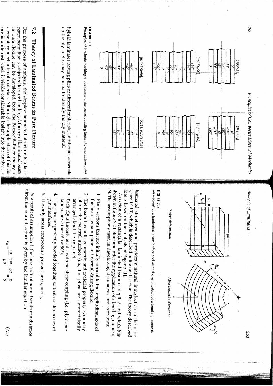
FIGURE 7.1 芦 ory is quite restricted,it yields considerable insight into the analysis of elementary mechanics of materials.Although the application of this the- in pure flexure can be developed from the Bernoulli-Euler theory of nated beam that is subjected to pure bending.A theory of laminated beams For the purpose of analysis,the simplest laminated structure is a lami- Theory of Laminated Beams in Pure Flexure on the ply angles may be used to identify the ply material. hybrid laminates having plies of different materials,additional subscripts Examples of laminate stacking sequences and the corresponding laminate orientation codes +45 115 45 160午44/009o 5。 e 。 446/02090s 10010035l 1(01700945l .300 1001305 Principles of Composite Material Mechanics FIGURE 7.2 z from the neutral surface is given by the familiar equation As a result of assumption 1,the longitudinal normal strain at a distance The only stress components present are o,and t ply interfaces 4.The plies are perfectly bonded together,so that no slip occurs at tations are either 0 or 90). 3.Each ply is linearly elastic with no shear coupling(ie.,ply orien- arranged about the xy plane). about the neutral surface (i.e.,the plies are symmetrically 2.The beam has both geometric and material property symmetry the beam remain plane and normal during flexure. 1.Plane sections that are initially normal to the longitudinal axis of M.The assumptions used in developing the analysis are as follows: shown in figure 7.2 before and after the application of a bending moment A section of a rectangular laminated beam of depth h and width b is here is based on the analysis of Pagano [1]. general CLT,which is described in the next section.The theory described laminated structures and provides a natural introduction to the more An element of a laminated beam before and after the application of a bending moment Before deformation Analysis of Laminates After flexural deformation E
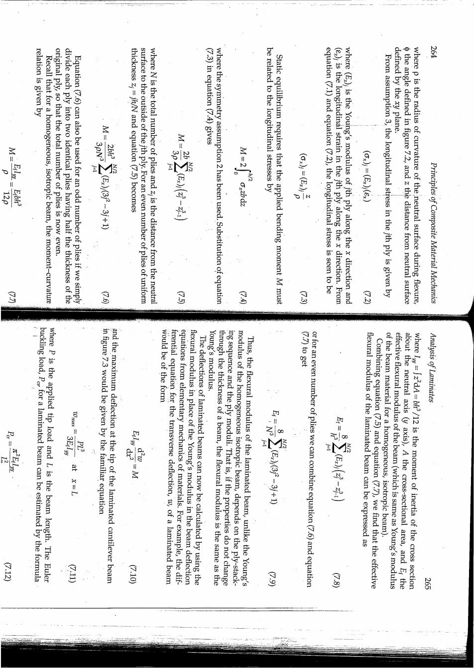
¥ relation is given by Recall that for a homogeneous,isotropic beam,the moment-curvature original ply,so that the total number of plies is now even. divide each ply into two identical plies having half the thickness of the Equation(7.6)can also be used for an odd number of plies if we simply (7.3)in equation (7.4)gives defined by the xy plane. 巴 20 thickness z;=jh/N and equation (7.5)becomes surface to the outside of the jth ply.For an even number of plies of uniform where N is the total number of plies and z is the distance from the neutral where the symmetry assumption 2 has been used.Substitution of equation be related to the longitudinal stresses by Static equilibrium requires that the applied bending moment M must equation(7.1)and equation(7.2),the longitudinal stress is seen to be (e,);is the longitudinal strain in the jth ply along the x direction.From where(E.);is the Young's modulus of ith ply along the x direction and From assumption 3,the longitudinal stress in the jth ply is given by the angle defined in figure 7.2,and z the distance from neutral surface where p is the radius of curvature of the neutral surface during flexure, Principles of Composite Material Mechanics 园 金 8 8 (7.7)to get buckling load,Pfor a laminated beam can be estimated by the formula where p is the applied tip load and L is the beam length.The Euler 三 in figure 7.3 would be given by the familiar equation and the maximum deflection at the tip of the laminated cantilever beam would be of the form Young's modulus. ferential equation for the transverse deflection,w,of a laminated beam equations from elementary mechanics of materials.For example,the dif- flexural modulus in place of the Young's modulus in the beam deflection The deflections of laminated beams can now be calculated by using the ing sequence and the ply moduli.That is,if the properties do not change through the thickness of a beam,the flexural modulus is the same as the modulus of the homogeneous isotropic beam,depends on the ply-stack- Thus,the flexural modulus of the laminated beam,unlike the Young's 冬 or for an even number of plies we can combine equation(7.6)and equation flexural modulus of the laminated beam can be expressed as Combining equation(7.5)and equation(7.7),we find that the effective effective flexural modulus of the beam(which is same as Young's modulus of the beam material for a homogeneous,isotropic beam). whereIw=zdA=/12 is the moment of inertia of the cross section about the neutral axis (y axis),A the cross-sectional area,and Ef the Analysis of Laminates 是 G10 8 品 务
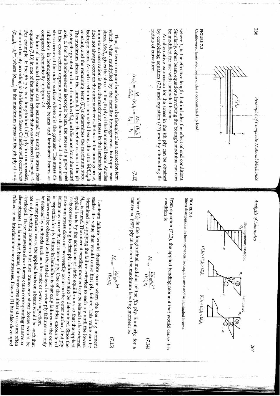
FIGURE 7.3 (Cmax)=s,where (max)is the maximum stress in the jth ply at z= failure in this ply according to the Maximum Stress Criterion will occur when For example,if the ith ply is a longitudinal (0)ply in compression, equation(7.13)in one of the failure criteria that was discussed in chapter 4. Failure of laminated beams can be estimated by using the stress from compared schematically in figure 7.4. tributions in homogeneous isotropic beams and laminated beams are stress occurs at the outer surface where z is the greatest.The stress dis- in the cross section depends only on the distance z,and the maximum axis,z.For the homogeneous isotropic beam,the stress at a given point having the greatest product of modulus(E,);and distance from the neutral The maximum stress in the laminated beam therefore occurs in the ply constant,and the remaining term (E)z determines the maximum stress. isotropic beam.At each section in a laminated beam,the ratio M/Eis does not always occur on the outer surface as it does in the homogeneous, important observation is that the maximum stress in the laminated beam stress,Mz/Iw gives the stress in the jth ply of the laminated beam.Another which when multiplied by the familiar homogeneous isotropic beam Thus,the term in square brackets can be thought of as a correction term, radius of curvature: by combining equation (7.3)and equation(7.7)and by eliminating the An alternative expression for the stress in the ith ply can be obtained be modified for use with laminated beams. Similarly,other beam equations involving the Young's modulus can now where Le is the effective length that includes the effect of end conditions. Cantilevered laminated beam under a concentrated tip load Principles of Composite Material Mechanics 会 condition is FIGURE 7.4 shear stresses.In laminated beams,the transverse shear stresses are often referred to as interlaminar shear stresses.Pagano [1]has also developed not only bending moments but also transverse shear forces would be developed.These transverse shear forces cause corresponding transverse be detected by methods such as ultrasonic or x-ray inspection. In most practical cases,the applied loads on a beam would be such that in inspection for ply failure in laminates is that only failures on the outer surfaces can be observed with the naked eye.Interior ply failures can only failure may occur in an interior ply.One of the difficulties encountered maximum stress does not necessarily occur on the outer surface,first ply applied loads by the equations of static equilibrium,so that the applied loads corresponding to first ply failure can also be determined.Since the Mis found.The internal bending moment can be related to the external reaches the value that would cause first ply failure.This value can be determined by applying the failure criterion to each ply until the lowest Laminate failure would therefore occur when the bending moment where(E);is the longitudinal modulus of the jth ply.Similarly,for a transverse (90)ply in tension the maximum bending moment is: From equation(7.13),the applied bending moment that would cause this Stress distributions in homogeneous,isotropic beams and in laminated beams. Analysis of Laminates 元ss 闐 公10

direction, FIGURE 7.5 多 static equilibrium of the element with respect to the forces along the x must act at the inner edge of the kth ply,as shown in figure 7.5.From under these normal stresses alone,the interlaminar shear stress, as shown in figure 7.5.Since the element cannot be in static equilibrium on the two faces of the jth ply in a differential element must be different, too,must the normal stress,o.This means that the normal stresses acting (7.13),we see that if the bending moment changes with respect to x,so, must change along the length of the beam(the x direction).From equation Thus,the presence of the shear force implies that the bending moment M,is related to the transverse shear force,V,by the equation Recall from the mechanics of materials [2]that the bending moment, stresses,as summarized here. 兵 a mechanics of materials approach for estimating these interlaminar shear for static equilibrium when the bending moment varies along the length. Differential element of a laminated beam showing interlaminar shear stress that is necessary ↓4 ↓@ +t号 Principles of Composite Material Mechanics 160 where which is where for a laminated beam Thus,the transverse shear stress is given by for a homogeneous isotropic beam equation for transverse shear stress in a homogeneous isotropic beam, Equation (7.20)is seen to be similar to the "mechanics of materials" for a rectangular beam having an even number of plies of uniform thick- ness,zj=jh/N,and equation (7.19)reduces to integrating,we find that the interlaminar stress at the inner edge of the Substituting equation (7.13)and equation(7.16)in equation(7.18)and Analysis of Laminates d(odz G23 G22 G211 (7.20) G13 多