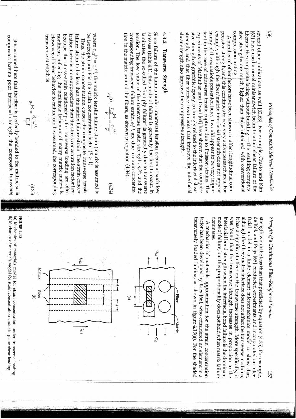
composites having poor interfacial strength,the composite transverse It is assumed here that the fiber is perfectly bonded to the matrix,so in transverse strength is However,if linear behavior to failure can be assumed,the corresponding nonlinear,reflecting the nonlinear behavior of many matrix materials. because the stress-strain relationships for transverse loading are often tration factor is more appropriate than the stress concentration factor here failure strain to be less than the matrix failure strain.The strain concen- compression testing. Thus,the strain concentration causes the composite transverse tensile wheree=e),the matrix tensile failure strain(matrix is assumed to be isotropic)and F is the strain concentration factor(F>1). tion in the matrix around the fibers,as shown in equation(4.34): tension.The low value of the transverse tensile strength,s,and the corresponding transverse failure strain,e),are due to strain'concentra- laminates,the so-called "first ply failure"is generally due to transverse stresses (table 4.1),this mode of failure is generally the first to occur.In Since failure of the lamina under transverse tension occurs at such low 4.3.2 Transverse Strength shear strength also improve the compressive strength. strength,and that fiber surface treatments that improve the interfacial sive strength of graphite/epoxy is strongly related to the interfacial shear experiments of Madhukar and Drzal [64]have shown that the compres- tant in the case of transverse tensile rupture due to Poisson strains.The in any of the equations presented here,it would appear to be very impor- example,although the fiber/matrix interfacial strength does not appear pressive strength,and this continues to be a very active research area.For A number of other factors have been shown to affect longitudinal com- sive strengths are much higher than those obtained with conventional fibers in the composite facing without buckling-the resulting compres- [63]have used a novel minisandwich beam to attain shear failure of the several other publications as well [62,63].For example,Crasto and Kim Principles of Composite Material Mechanics FIGURE 4.13 dominates. (b)Mechanics of materials model for strain concentration under in-plane shear loading. (a)Mechanics of materials model for strain concentration under transverse loading. transversely loaded lamina, as shown in figure 4.13(a).For the shaded factor has been developed by Kies [661,who considered an element in a A mechanics of materials approximation for the strain concentration mode of failure,but this proportionality does not hold when matrix failure interfacial bond strength when the interfacial bond failure is the dominant was found that the transverse strength increases in proportion to the it has a significant effect on the transverse strength.More specifically,it although the fiber/matrix interface does not affect the transverse modulus, facial model in a finite element micromechanics model to show that, de Kok and Peijs [65]conducted experiments and incorporated an inter- strength would be less than that predicted by equation(4.35).For example, Strength of a Continuous Fiber-Reinforced Lamina

factor 云 compressive strength,s(),by replacing the tensile strains or strengths The same method outlined above can be used to estimate the transverse fibers,we pay the penalty of lower composite transverse strength! properties by using higher fiber volume fractions and higher modulus noteworthy.Thus,as we strive to improve the composite longitudinal figure 4.14 for Em/E<1[69].The sharp rise in F for vr>0.6 is particularly example,the variation of F with fiber volume fraction is shown in concentration factor increases with increasing v and increasing E2.For It is important to note that according to equation(4.38),the strain by a finite difference solution of the theory of elasticity model [68]. transverse composite yield strain [67].A slightly higher value is predicted transverse composite failure strain or the ratio of matrix yield strain to imentally determined values based on the ratio of matrix failure strain to matrix(v;=0.45)is F=3.00.This value is in good agreement with exper- concentration factor for a triangular array of E-glass fibers in an epoxy listed in equations(3.29)in equation(3.12)and equation(4.38),the strain fiber volume fraction,v.For example,from substitution of the properties (3.12)that the ratio of fiber diameter to fiber spacing,d/s,is related to the the assumption of isotropy.Recall from equation (3.10)and equation where the subscript"2"for matrix properties has been dropped due to 8 之3 which can be rearranged to give the expression for the strain concentration Equation(4.36)can then be written as that each material satisfies Hooke's law(eqs.[3.341),as in section 3.2.2. assumed that the stresses in composite,matrix,and fiber are equal and series arrangement of fiber and matrix materials in the shaded strip,it is where the symbols are:defined in section 3.2.2 and figure 4.13(a).For the the deformations in the fiber and matrix strip shown in figure 4.13(a),the total elongation is found by summing Principles of Composite Material Mechanics (4.30) stress permission.) FIGURE 4.14 Strain con centration factor,For F ing occurs in the matrix when the equivalent axial stress or von Mises increases with increasing v the transverse failure strain decreased with increasing r(fig.4.16).According to the von Mises yield criterion,yield- fiber volume fraction(fig.4.15),but since the transverse modulus,E2,also on the von Mises failure criterion for the epoxy matrix showed that the transverse strength of the composite increased slightly with increasing of glass/epoxy using experiments and finite element micromechanical models.Experiments and a finite element micromechanical model based sincreases slightly with increasing v.For example,de Kok and Meijer [71]studied the effect of fiber volume fraction on the transverse strength 3 decreases with increasing v:,there is some evidence in the literature that around fibers and/or voids,or longitudinal fiber splitting [70]. While substitution of equation(4.38)in equation(4.35)shows that s() because of fiber/matrix interfacial bond failure,strain concentrations composite strength,but the actual composite strength would be lower with the corresponding compressive strains or strengths.Alternatively, the corresponding matrix strength can be used as an upper bound on the Composite Materials,vol.5,Fracture and Fatigue,Chapter 3.Academic Press,New York.With Variation of strain concentration factor For F,with fiber volume fraction.Valid for F when EE1 and for F,when G/Gn21.(From Chamis,C.C 1974.In Broutman,L.J.ed., 3 Fiber volume fraction,D 圣 Strength of a Continuous Fiber-Reinforced Lamina (9·39

FIGURE 4.16 ·15 FI A.Annlied Srience and Manufacturing.30.905-916.With permission.) lines)and hexagonal (dotted lines)fiber packing models,using a von Mises criterion and Transverse failure strain (% Transverse strength(MPa) an ultimate stress criterion.(From de Kok,J.M.M.and Meijer,H.E.H.1999.Composites Part as measured in tension(o)and three point bending(),and predicted with the square(solid Transverse failure strain of E-glass/epoxy composite as a function of fiber volume fraction, 00 Fiber volume fraction (% A:Applied Science and Manufuacturing,30,905-916.With permission.) an ultimate stress criterion.(From de Kok,J.M.M.and Meijer,H.E.H.1999.Composites Part measured in tension (o)and three point bending(),and predicted with the square(solid lines)and hexagonal (dotted lines)fiber packing models,using a von Mises criterion and Transverse strength of E-glass/epoxy composite as a function of fiber volume fraction,as Fiber volume fraction(%) Principal stress von Mises stress Principal stress von Mises stres Principles of Composite Material Mechanics where plane shear strains or strengths.Again,the matrix shear strength can be used as an upper bound on the composite shear strength,as the actual other necessary equations are obtained by replacing the tensile strains or strengths in equation(4.34)and equation(4.35)with the corresponding in- 414元190××1 fig fig fig previous comments regarding the effect of v;on F are also valid for F The Note that this equation has the same form as equation (4.38).Thus, Gn2=fiber in-plane shear modulus Yn2=average fiber in-plane shear strain Yez=average composite in-plane shear strain Ym2=average matrix in-plane shear strain and the in-plane shear strain concentration factor is figure 4.13(b),the expression analogous to equation(4.36)for the in-plane shear strain is outlined in the previous section.For the shaded element shown in The in-plane shear strength,s can also be estimated using the procedure 4.3.3 In-Plane Shear Strength corresponding prediction based on the actual triaxial state of stress and the von Mises failure criterion. 8782-4782+8-08m12 dicted transverse strength based on the 1-D stress model described in equation(4.34)to equation(4.38)is conservative by comparison with the the ultimate principal stress model(fig.4.15).So it appears that the pre- chanics model.In addition,the predicted transverse strength based on the von Mises criterion was significantly higher than that predicted by predicted transverse strength decreased with increasing v when only the ultimate principal stress in the matrix was considered in the microme- reaches the uniaxial yield strength of the matrix material,where oo and o.are the three principal stresses in the matrix.The corresponding Strength of a Continuous Fiber-Reinforced Lamina (42) (440) 三

百 previous section. strength under other types of loading such as interlaminar shear and have been discussed here.More detailed micromechanics analyses of In conclusion,only the basics of micromechanical strength prediction range 30<0<60. the lowest strength prediction of the two criteria worked best in the best agreement in the range 600<0<90,and the criterion that gave tions in the range 0<0<30,the Maximum Stress Criterion gave the showed the best agreement with the DMM approach for fiber orienta- the composite.For off-axis tensile test models,the Tsai-Wu criterion fiber/matrix interface played dominant roles in the failure criteria for biaxial stress space,and that the failure criteria for the matrix and the imum stress criteria led to the most conservative failure envelope in the. examined,it was found that the combination of the Tsai-Wu and max- agrees best with the Tsai-Wu prediction.From all the different cases strain criteria.For the case shown in figure 4.17,the DMM prediction DMM with those from the Tsai-Wu and maximum stress and maximum stress criteria.Figure 4.17 shows a comparison of failure envelopes from Maximum Strain Criterion,and the combined Tsai-Wu and maximum stresses in the Tsai-Wu criterion,the Maximum Stress Criterion,the envelopes that were generated using the applied macromechanical erated using the DMM and compared with the corresponding failure and the maximum interfacial shear stress.Failure envelopes ,were gen- ment level was modeled using the maximum tensile interfacial stress (b)von Mises criterion,while fiber/matrix interfacial failure at the ele- each element of the model:(a)maximum principal stress criterion and matrix materials were employed in the DMM for predicting failure in mechanics method (DMM).Two types of failure criteria for the fiber and unidirectional composite.The approach was referred to as a direct micro- and maximum stress criteria for several biaxial loading conditions on a mum stress and Tsai-Wu criteria as well as the combination of Tsai-Wu unit cell micromechanics models and used them to evaluate the maxi- For example,Zhu,Sankar,and Marrey [72]developed finite element evaluate multiaxial failure criteria such as those described in section 4.2. these areas.However,micromechanical models have also been used to of the micromechanical strength modeling efforts have been focused in for prediction of the five basic unidirectional lamina strengths,and most Section 4.3.1 to section 4.3.3 have summarized micromechanical models 4.3.4 Multiaxial Strength composite strength would be lower for the same reasons mentioned in the Principles of Composite Material Mechanics The matrix tensile failure strain is EXAMPLE 4.5 FIGURE 4.17 Solution.The fiber tensile failure strain is Normal stress in transverse direction (X direction)(GPa 3.05 0.103 en)0.011 2220 strengths of fiber and matrix materials are 2413 and 103 MPa,respectively. material described in example 3.1,example 3.2,and example 3.4 if the tensile Determine the longitudinal and transverse tensile strengths of the carbon/epoxy on strength have been summarized by Chamis [69] flexure as well as micromechanical effects of voids and residual stresses Materials,32,766-782.With permission.) 010 imum Strain Criterion in the prediction of failure envelopes for a unidirectional composite under biaxial loading.(From Zhu,H.,Sankar,B.V.,and Marrey,R.V.1998.Journal of Composite Comparison of results from DMM,Tsai-Wu criterion,Maximum Stress Criterion,and Max- 020 Normal stress in fiber direction(X3 direction)(GPa) Strength of a Continuous Fiber-Reinforced Lamina ---Maximum strain criterion -Maximum stress criterion ---Direct micromechanics method .Tsai-Wu criterion
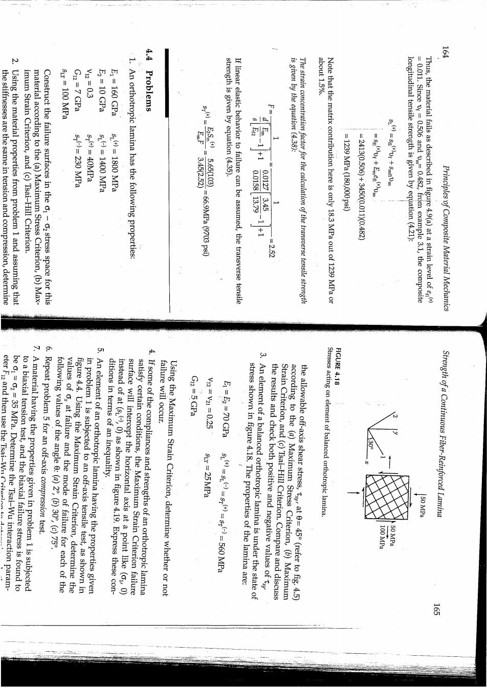
G12=7 GPa V2-0.3 E2=10 GPa ·4 4. abo1t1.570 the stiffnesses are the same in tension and compression,determine Using the material properties from problem 1 and assuming that imum Strain Criterion,and (c)Tsai-Hill Criterion. SLr=100 MPa E1 =160 GPa material according to the (a)Maximum Stress Criterion,(b)Max- Construct the failure surfaces in the o1-02 stress space for this is given by the equation (4.38): s)=230 MPa s()=40MPa 580-1400MPa SL.()=1800 MPa 1.An orthotropic lamina has the following properties: 3SM565109 strength is given by equation (4.35). 3452.52 If linear elastic behavior to failure can be assumed,the transverse tensile The strain concentration factor for the calculation of the transverse tensile strength Note that the matrix contribution here is only 18.3 MPa out of 1239 MPa or -1239MPa18000029) -2413(0.506)+34500.0110(0.482) SL()=SDi+8mfiVm longitudinal tensile strength is given by equation(4.21): =2.52 =0.011.Since vr=0.506 and v=0.482,from example 3.1,the composite Thus,the material fails as described in figure 4.9(a)at a strain level of e) Principles of Composite Material Mechanics FIGURE 4.18 eter Fi2 and then use the Tsai-Wnr 7.A material having the properties given in problem 1 is subjected to a biaxial tension test,and the biaxial failure stress is found to be c1=02=35 MPa.Determine the Tsai-Wu interaction param- 6.Repeat problem 5 for an off-axis compression test. following values of the angle 6:(a)2,(b)30%,(c)75. values of o,at failure and the mode of failure for each of the figure 4.4.Using the Maximum Strain Criterion,determine the 5.An element of an orthotropic lamina having the properties given in problem 1 is subjected to an off-axis tensile test,as shown in ditions in terms of an inequality. surface will intercept the horizontal axis at a point like (oL,0) instead of at (s,0)as shown in figure 4.19.Express these con- 4.If some of the compliances and strengths of an orthotropic lamina satisfy certain conditions,the Maximum Strain Criterion failure Using the Maximum Strain Criterion,determine whether or not failure will occur. G12=5GPa V2-V110.25 Sur 25MPa (40-60-S40-9O-g602ra 3.An element of a balanced orthotropic lamina is under the state of stress shown in figure 4.18.The properties of the lamina are: the results and check both positive and negative values of Strain Criterion,and (c)Tsai-Hill Criterion.Compare and discuss according to the (a)Maximum Stress Criterion,(b)Maximum the allowable off-axis shear stress,tat 0=45(refer to fig.4.5) Stresses acting on element of balanced orthotropic lamina. Strength of a Continuous Fiber-Reinforced Lamina 50 MPa 100 MPa 50 MPa