Experiment 4 RLC Circuits The resistance,the electric capacitance and the inductance are basic elements for electric circuit. Series circuit constituted by RC,RL or RLC has different features,including the transient behavior,the steady-state characteristic,resonance characteristic.They all play an important role in applications.In this experiment,the transient and continuous periodic electric signals are observed and investigated by a digital storage oscilloscope,since the oscilloscope has a lot of useful functions 【Objectives.】 1.Study the basic operations on a digital storage oscilloscope; 2.Through the study on RC,RL and RLC series circuit's transient process,understand the electric charge and discharge rule of capacitor,electromagnetic induction characteristic of the inductor and the damping of oscillation circuit; 3 How to measure the amplitude frequency characteristic and the phase frequency characteristic of RC,RL and the RLC series circuits; 4 Survey the RLC electric circuit of the resonance frequency.Find the quality factor Q according to the amplitude-frequency curve. 【Principle】 1.The basic operations on a digital storage oscilloscope a.Observation and measurement of parameters of a continuous time signal using oscilloscope. b.Measurement of phase difference. Fig.I shows a phase-shifting circuit.There is a phase difference between the voltage of the input signal and the capacitor as shown in Fig.2.According to vector diagram of the voltage of signal generator and resistor (Fig.3),three ways can be expected to obtain the phase Fig 1 RC phase shifting circuit difference. △T △0=2π T (1) UR Fig 2 Two sinusoidal waves with a phase difference Fig 3 Vector diagram of Uc.UR
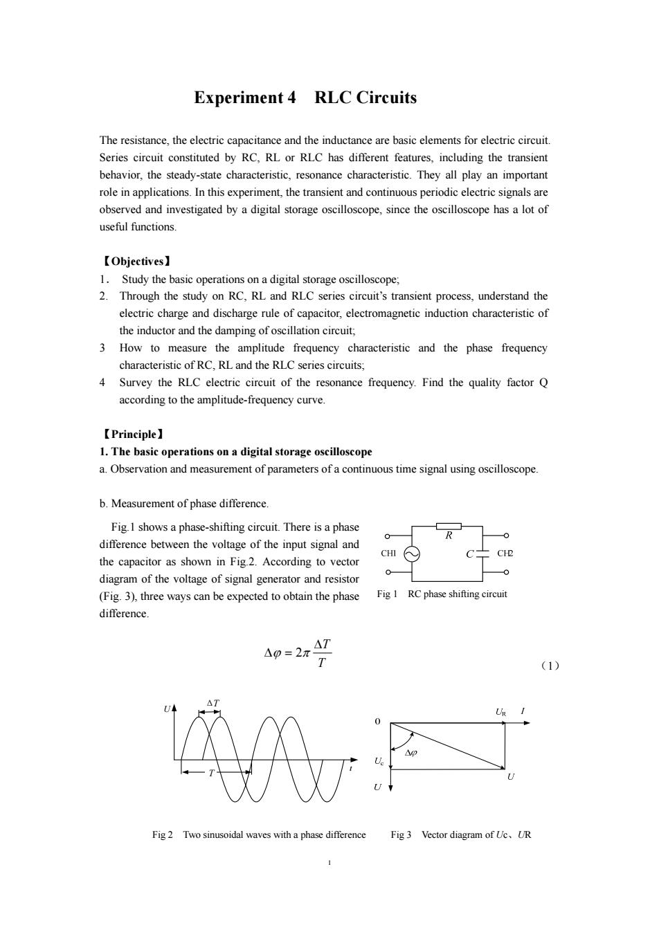
1 Experiment 4 RLC Circuits The resistance, the electric capacitance and the inductance are basic elements for electric circuit. Series circuit constituted by RC, RL or RLC has different features, including the transient behavior, the steady-state characteristic, resonance characteristic. They all play an important role in applications. In this experiment, the transient and continuous periodic electric signals are observed and investigated by a digital storage oscilloscope, since the oscilloscope has a lot of useful functions. 【Objectives】 1. Study the basic operations on a digital storage oscilloscope; 2. Through the study on RC, RL and RLC series circuit’s transient process, understand the electric charge and discharge rule of capacitor, electromagnetic induction characteristic of the inductor and the damping of oscillation circuit; 3 How to measure the amplitude frequency characteristic and the phase frequency characteristic of RC, RL and the RLC series circuits; 4 Survey the RLC electric circuit of the resonance frequency. Find the quality factor Q according to the amplitude-frequency curve. 【Principle】 1. The basic operations on a digital storage oscilloscope a. Observation and measurement of parameters of a continuous time signal using oscilloscope. b. Measurement of phase difference. Fig.1 shows a phase-shifting circuit. There is a phase difference between the voltage of the input signal and the capacitor as shown in Fig.2. According to vector diagram of the voltage of signal generator and resistor (Fig. 3), three ways can be expected to obtain the phase difference. T ΔT Δϕ = 2π (1) t U T ΔT Fig 2 Two sinusoidal waves with a phase difference Fig 3 Vector diagram of Uc、UR Fig 1 RC phase shifting circuit
c.Measurement of a transient signal (Optional) As is illustrated in Fig.4,a flashing lamp is a HID(High Intensity Discharge)light that is filled with high-pressured xenon gas,which would be swiftly ionized and form a voltaic arc when there is a high voltage between two electrodes,and meantime the resistance of which drops drastically so that a strong current occurs.An energy storing capacitor must be needed to maintain the discharging.The initial ionization is triggered by a high pressured impulse,and in the process of discharge,the energy stored in the capacitor is consumed swiftly and so is the voltage between the capacitor,so when the process are no longer able to be maintained,the flash ends.If the capacitance of the capacitor is small,this process is extremely short in the order of magnitude of microseconds. As for observing the flashing process,a proper photoelectric sensor should be chosen so that the response time will be as short as possible.Here we provide two types of photoelectric sensors. One is a silicon photoelectric diode of PIN type with a small area,which has a layer of intrinsic material that enables a lower capacity,a faster response and a better linear property when inversely biased.Another is Cds photosensitive resistor,whose response time is relatively long and which is not proper to be used for a quick measurement.Here the Cds is merely for a reference.The sampling resistance in the quick measurement also needs to be low in order to minimize the lost of the high-frequency part of the signal. In Fig.4,Ce is the energy-storing capacitor,R is the current sampling resistor in discharge process,R2 is the sampling resistor for the photoelectric current from photoelectric sensor D.Ce is in parallel with the flashing lamp.With this circuit,we can simultaneously measure the discharge current of capacitor Ce and the signal of flash. If the voltage between Ce is Ve and Va before and after discharging,then the total energy output of Ce is E.-c.- (2) We can also roughly estimate the power input Pr of the flashing lamp by taking the half-width of the photoelectric current at the time interval.However,Pr is much affected by the conversion efficiency of flash lamp. 90% 50% 10% Fig5 The transient signal of the two sampling resistors 2
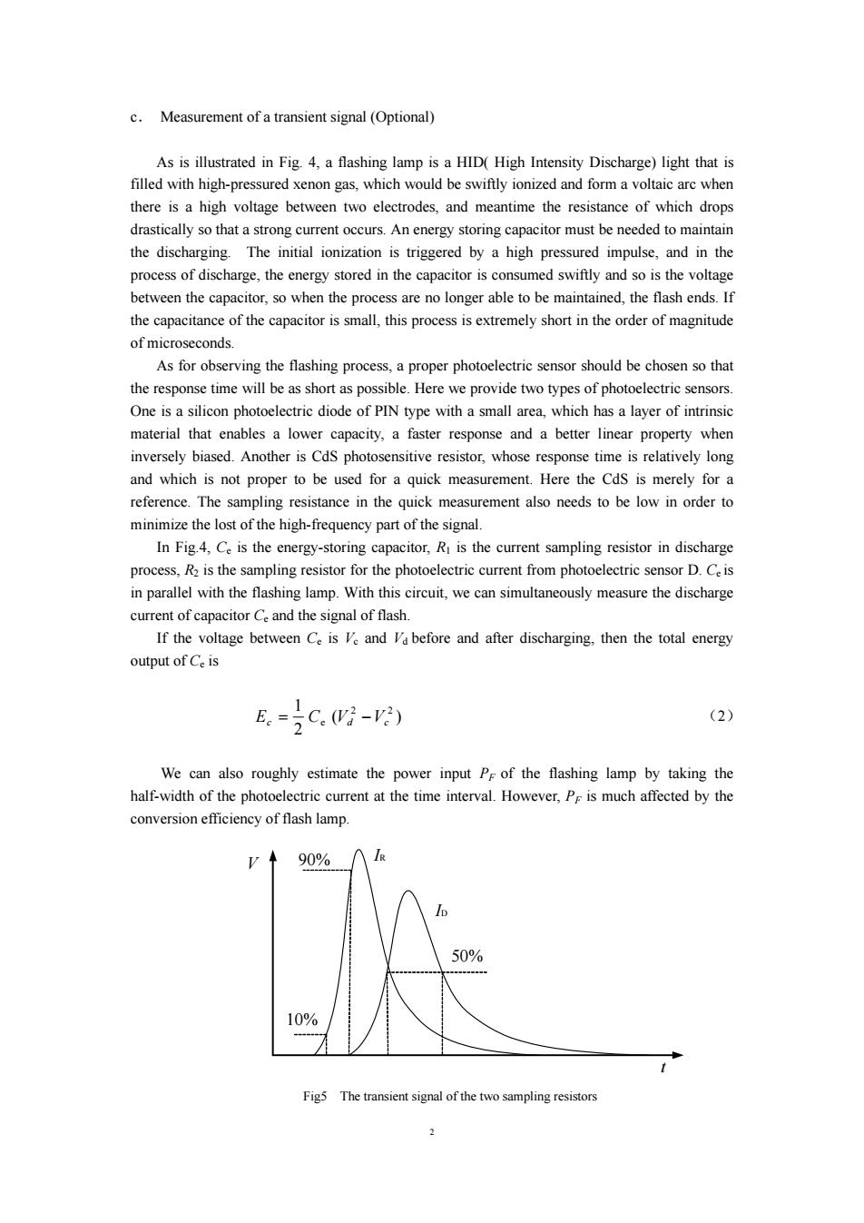
2 c. Measurement of a transient signal (Optional) As is illustrated in Fig. 4, a flashing lamp is a HID( High Intensity Discharge) light that is filled with high-pressured xenon gas, which would be swiftly ionized and form a voltaic arc when there is a high voltage between two electrodes, and meantime the resistance of which drops drastically so that a strong current occurs. An energy storing capacitor must be needed to maintain the discharging. The initial ionization is triggered by a high pressured impulse, and in the process of discharge, the energy stored in the capacitor is consumed swiftly and so is the voltage between the capacitor, so when the process are no longer able to be maintained, the flash ends. If the capacitance of the capacitor is small, this process is extremely short in the order of magnitude of microseconds. As for observing the flashing process, a proper photoelectric sensor should be chosen so that the response time will be as short as possible. Here we provide two types of photoelectric sensors. One is a silicon photoelectric diode of PIN type with a small area, which has a layer of intrinsic material that enables a lower capacity, a faster response and a better linear property when inversely biased. Another is CdS photosensitive resistor, whose response time is relatively long and which is not proper to be used for a quick measurement. Here the CdS is merely for a reference. The sampling resistance in the quick measurement also needs to be low in order to minimize the lost of the high-frequency part of the signal. In Fig.4, Ce is the energy-storing capacitor, R1 is the current sampling resistor in discharge process, R2 is the sampling resistor for the photoelectric current from photoelectric sensor D. Ce is in parallel with the flashing lamp. With this circuit, we can simultaneously measure the discharge current of capacitor Ce and the signal of flash. If the voltage between Ce is Vc and Vd before and after discharging, then the total energy output of Ce is ( ) 2 1 2 2 Ec = Ce Vd −Vc (2) We can also roughly estimate the power input PF of the flashing lamp by taking the half-width of the photoelectric current at the time interval. However, PF is much affected by the conversion efficiency of flash lamp. V t IR ID 10% 90% 50% Fig5 The transient signal of the two sampling resistors

Through the sampling resistance Ri,we can measure the peak voltage Vp of Ri and thus the peak power of the sampling resistance Ri is PR =Vp2 /R (3) The rising slope di/dt can be evaluated with reference to the change from the 10%to 90%of the peak value. 2.The transient process of RC.RL RLC circuits (1)series RC circuits. As shown in Fig.6,electric capacity charge and discharges during the transient process.The signal source supply square-wave signal.During the first half cycle,the voltage of source is +E.it charges the capacitor;the square-wave voltage turns to 0 in the second half cycle,the capacity discharges.The equation of charging process is Fig6 Series RC circuit RCUc+Ue=E dt (4) Initial condition:t=0 =>Uc=0, Uc=E(1-e RC) Ug =iR=Ee RC (5) From the equation of Uc,UR,Uc increases with time t by exponential law,while resistance voltage Ug decrease in the same way,as shown in Fig.7,therein displaying U-t Uc-t、UR-1 curves.. The equation of discharging process: Rcde+U。=0 UR dr (6) Initial condition:t=0,=>U=E thus we have Uc Ee R UR=R=-Ee旋 (8) From the equation of Uc.Ug,they both decay with time Fig 7 Charging and discharging by exponential law.RC=,which has the dimension of process of series RC circuit
3 Through the sampling resistance R1, we can measure the peak voltage VP of R1 and thus the peak power of the sampling resistance R1 is 1 2 1 PR = Vp / R (3) The rising slope di/dt can be evaluated with reference to the change from the 10% to 90% of the peak value. 2.The transient process of RC、RL、RLC circuits (1)series RC circuits. As shown in Fig. 6, electric capacity charge and discharges during the transient process. The signal source supply square-wave signal. During the first half cycle, the voltage of source is +E. it charges the capacitor; the square-wave voltage turns to 0 in the second half cycle, the capacity discharges. The equation of charging process is U E t U RC C C + = d d (4) Initial condition: t = 0 => UC = 0, RC t R RC t C U iR Ee U E e − − = = = (1− ) (5) From the equation of UC、UR , UC increases with time t by exponential law, while resistance voltage UR decrease in the same way, as shown in Fig.7, therein displaying U – t、 UC – t、UR – t curves. The equation of discharging process: 0 d d + C = C U t U RC (6) Initial condition: t = 0,=>UC = E thus we have RC t R RC t C U iR Ee U Ee − − = = − = (8) From the equation of UC、UR , they both decay with time by exponential law. RC =τ, which has the dimension of Fig 7 Charging and discharging process of series RC circuit Fig6 Series RC circuit

time,is called time constant.It is an important physical quantity to characterize the speed of transient process.Another characteristic number related with time constant r is so called half-value time Ti,which means half of time that Uc(t)decrease to its initial value or increase to a terminal value.It is also used to describe the speed of transient process.The relationship between Tin and r is: T12=ln2=0.693(ort=1.443T1n) (9) (2)series RL circuits The analysis is similar to RC circuits.Through which we can obtain the time constant r and half-value time Ti: ÷上,T2=0.693x=0.6931 (10) (3)series RLC circuit. Firstly,discuss the condition that a power supply is turned on suddenly,the equation of capacitor voltage Uc is LCU+RC Uc+Ve=E dt2 dt (11) Divide by LC on both sides,and let B=R/2L and 00= LC (12) Then the Eq.11 changes into: dU+260+U。=ogE dr2 dt (13) Eq.13 is a typical equation of damped oscillation.B is damping coefficient,@o is the natural frequency of the circuit.Together with the two initial condition of this process: dUc =0 =0:dr o (14) Therefore,the solution to Eq.13 depends on the ratio ofB and @o. 4
4 time, is called time constant. It is an important physical quantity to characterize the speed of transient process. Another characteristic number related with time constant τ is so called half-value time T1/2, which means half of time that UC(t)decrease to its initial value or increase to a terminal value. It is also used to describe the speed of transient process. The relationship between T1/2 and τ is: T1/2 =τln2 = 0.693(or τ = 1.443T1/2) (9) (2)series RL circuits The analysis is similar to RC circuits. Through which we can obtain the time constant τ and half-value time T1/2: R L T R L τ = , 1 / 2 = 0.693τ = 0.693 (10) (3)series RLC circuit. Firstly, discuss the condition that a power supply is turned on suddenly, the equation of capacitor voltage UC is U E t U RC t U LC C C C + + = d d d d 2 2 (11) Divide by LC on both sides,and let β = R 2L and LC 1 ω0 = (12) Then the Eq.11 changes into: U E t U t U C C C 2 0 2 2 0 2 d d 2 d d + β + ω =ω (13) Eq. 13 is a typical equation of damped oscillation. β is damping coefficient,ω0 is the natural frequency of the circuit.Together with the two initial condition of this process: 0 0 = C t= U ; 0 d d 0 = t= C t U (14) Therefore, the solution to Eq. 13 depends on the ratio of β and ω0.
The result is discussed under three different conditions as following: (1)underdamping wheniscalled underdamping,the solution is Uc=E-Ee-R cos+ (15) WhereEq.15 is called damping oscillation solution. (2)overdamping when0,it is called overdamping. The solution is Ue=E-号ele+水--7k 2r (16) Where,there is no oscillation in this case. (3)critical damping when0 it iscalled critical damping,the solution is U=E-E(1+Bte- (17) When the circuit achieves steady state,dropping the power supply suddenly(E-0),the changes periodic damping U square wave critical damping Fig8 Charge&discharge wave pattern of series RLC circuit
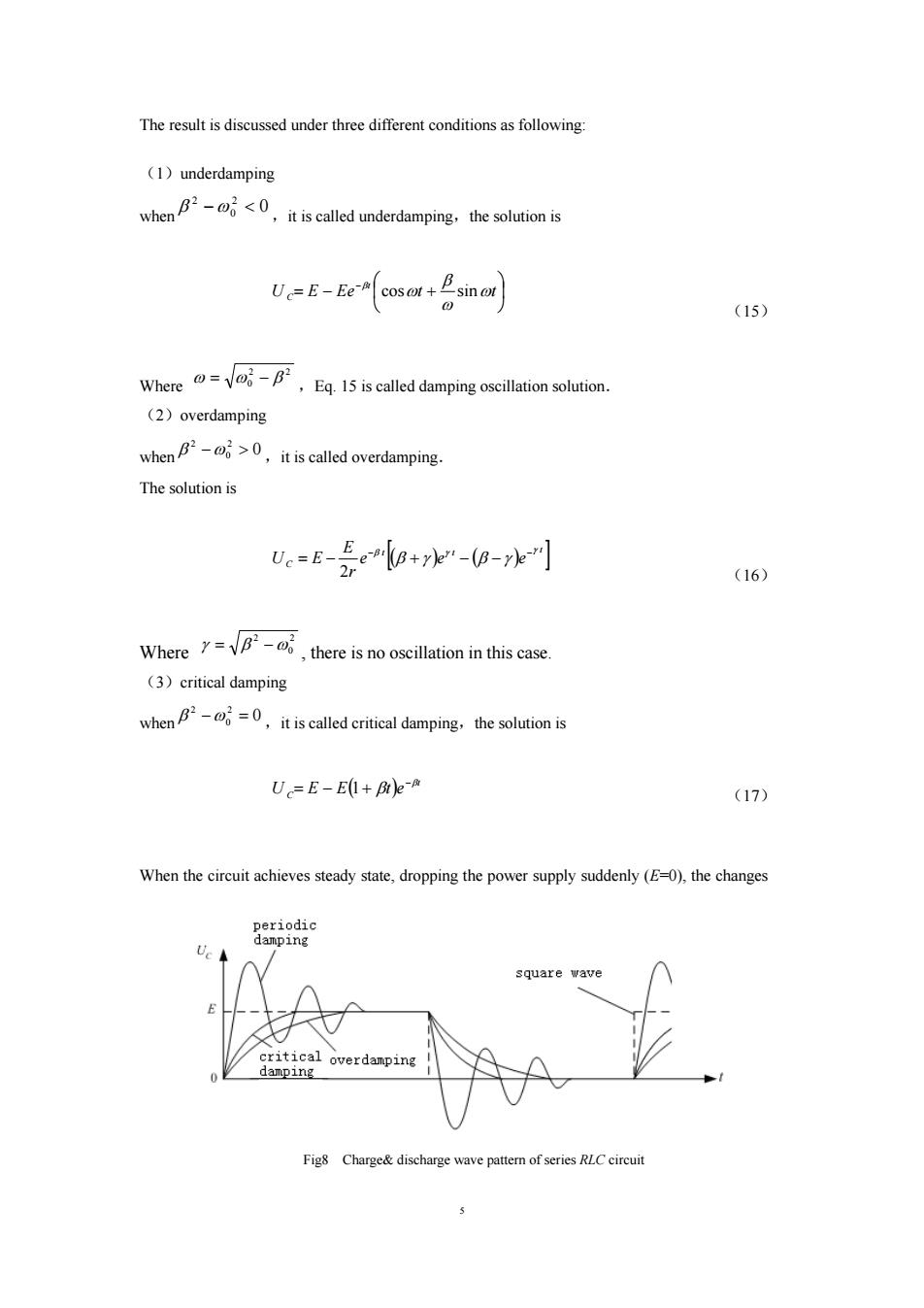
5 The result is discussed under three different conditions as following: (1)underdamping when 0 2 0 2 β −ω < ,it is called underdamping,the solution is ⎟ ⎠ ⎞ ⎜ ⎝ ⎛ = − + − U E Ee t t t C ω ω β ω β cos sin (15) Where 2 2 ω = ω0 − β ,Eq. 15 is called damping oscillation solution. (2)overdamping when 0 2 0 2 β −ω > ,it is called overdamping. The solution is [( )( ) ]t t t C e e e r E U E 2 γ β γ β γ β γ − − = − + − − (16) Where 2 0 2 γ = β −ω , there is no oscillation in this case. (3)critical damping when 0 2 0 2 β −ω = ,it is called critical damping,the solution is ( ) t C U E E t e β β − = − 1+ (17) When the circuit achieves steady state, dropping the power supply suddenly (E=0), the changes Fig8 Charge& discharge wave pattern of series RLC circuit